
1. Manual FX
Compared to System Effects, Manual FX is more intricate. It provides multiple parameters for the user to achieve nuanced control and personalized creation. Users can create many kinds of custom lighting effects via adjusting the parameters. With these features, Manual FX can fulfill a variety of requirements for a project.
1.1 Source Base
The two kinds of Source Base for Manual FX are CCT and HSI modes.
- Source Base: CCT or HSI mode
- CCT mode as source base: The user can change the color temperature, G/M and intensity.
- HSI mode as source base: The user can change the HUE, SAT and intensity.
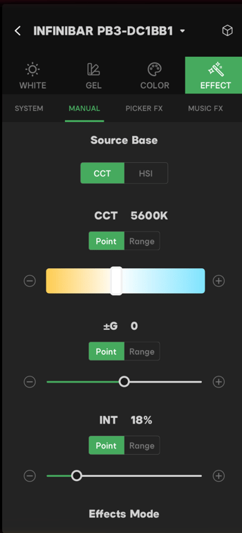 Figure 1.1 Source Base Mode
Note:
The user can adjust the G/M, only when the fixture supports G/M adjustment.
1.2 Point and Range
1.2.1 Point
When the users set the parameter as point, the parameter remains in a certain value.

- In CCT mode, the user can set specific values for color temperature, G/M and intensity.
- You can only choose a color temperature value within the fixtures color temperature range.
- G/M setting range: G1.0 to M1.0
- Intensity setting range: 0% to 100%
- In the HSI mode, the user can set specific values for HUE, SAT and intensity.
- HUE setting range: 0° to 359.9°
- SAT setting range: 0% to 100%
- Intensity setting range: 0% to 100%
Note:
Check the fixtures specifications to know the adjustable range of its parameters.
1.2.2 Range
When the user sets the parameter as range, the parameter varies along with the selected mode, within the selected range.

Range chase mode
- Sequential
 : Vary from minimum to maximum within the selected range
 - Reverse
 : Vary from maximum to minimum within the selected range
 - Alternating
 : Vary from maximum to minimum and then vary back from minimum to maximum within the selected range
 - Random
 : Vary with random value within the selected range
1.2.3 Manual FX Effects Mode
Manual FX Effects Modes: Flash, Continuous and Segmented
-
Flash mode. The intensity and color of the fixture remain the same in one active unit. For example, the system produces several different active units to execute the command of color chase on a fixture;
-
Continuous mode. The intensity and color of the fixture vary in one active unit. For example, the system produces one active unit to execute the command of color chase on a fixture;
-
Segmented mode. Segmented mode combines the features of both Flash mode and Continuous mode.
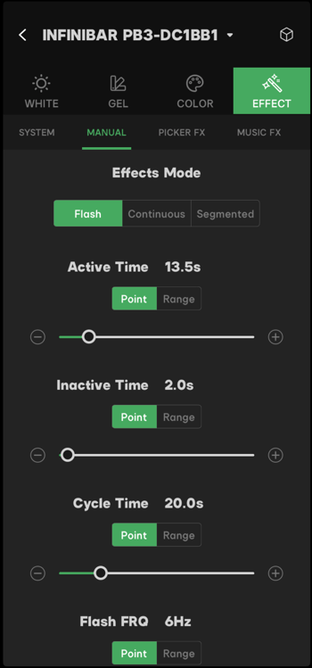
Figure 1.2.3-1 Effect Modes
Flash Mode
- The active time can be adjusted from 0 - 100 seconds in point mode. Set the active time from 0 - 100 seconds in range mode. Check the range chase mode details in 1.2.2 Range.
- The inactive time can be adjusted from 0 - 100 seconds in point mode. Set the inactive time from 0 - 100 seconds in range mode. Check the range chase mode details in 1.2.2 Range.
- Active time plus inactive time is one cycle unit. Cycle Time is the length of one cycle unit. The cycle time can be adjusted from 0 - 100 seconds in point mode. Set the cycle time from 0 - 100 seconds in range mode. Check the range chase mode details in 1.2.2 Range;
- Flash FRQ: Low flash frequency increases the fixture flash on time. High flash frequency decrease the fixtures on time. The Flash FRQ can be adjusted from 0.1Hz - 120Hz in point mode. Set the Flash FRQ from 0.1Hz - 120Hz in range mode. Check the range chase mode details in 1.2.2 Range.
Figure 1.2.3-1 Flash Mode
Continuous Mode
- Fade-in Time/Fade-out Time is the time from when the fixture is on/off until the fixture reaches a certain intensity. Users can set the Fade-in Time/Fade-out Time as point or range mode. The Fade-in Time/Fade-out Time can be adjusted from 0 - 100 seconds in point mode. Set the Fade-in Time/Fade-out Time from 0 - 100 seconds in range mode. Check the range chase mode details in 1.2.2 Range.
- The type of Fade-in Curve/Fade-out Curve's are Linear, Exponential, Logarithmic and S-curve. In Linear mode, the intensity of the fixture varies with uniform speed. In Exponential mode, the intensity of the fixture varies with the slow speed in the beginning and accelerates towards the end of the curve. In Logarithmic mode, the intensity of the fixture is accelerated in the beginning and decelerate towards the end of the curve. In S-curve mode, the intensity of the fixture varies with slow changes in the beginning and the end of the curve and accelerated changes in the middle of the curve.
- One cycle unit is the Fade-in Time, continue time and Fade-out Time. Cycle Time is the length of one cycle unit. The cycle time can be adjusted from 0 - 100 seconds in point mode. Set the cycle time from 0 - 100 seconds in range mode. Check the range chase mode details in 1.2.2 Range.
- Flash FRQ: Low flash frequency increases the fixtures on time. High flash frequency decrease the fixtures on time. The Flash FRQ can be adjusted from 0.1Hz - Flicker Free.
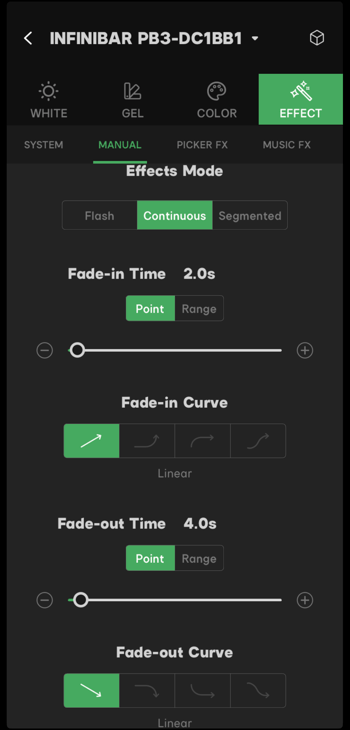
Figure 1.2.3-2 Continuous Mode
Segmented Mode
- The active time can be adjusted from 0 - 100 seconds in point mode. Set the active time from 0 - 100 seconds in range mode. Check the range chase mode details in 1.2.2 Range.
- Fade-in time/Fade-out time is the time from the fixture is on/off till the fixture reaches a certain intensity. Users could set the Fade-in time/Fade-out time as point mode or range mode. The Fade-in time/Fade-out time can be adjusted from 0 - 100 seconds in point mode. Set the Fade-in time/Fade-out time from 0 -100 seconds in range mode. Check the range chase mode details in 1.2.2 Range.
- The type of Fade-in curve/ Fade-out curves are Linear, Exponential, Logarithmic and S-curve.
- In Linear mode, the intensity of the fixture varies with uniform speed.
- In Exponential mode, the intensity of the fixture varies with slow speed in the beginning and accelerated speed towards the end of the variation.
- In Logarithmic mode, the intensity of the fixture varies with accelerated speed in the beginning and slower speed in the towards the end of the variation.
- In S-curve mode, the intensity of the fixture varies with the slow speed in the beginning and the ending parts and accelerated speed in the middle.
- The inactive time can be adjusted from 0 - 100 seconds in point mode. Set the inactive time from 0 - 100 seconds in range mode. Check the range chase mode details in 1.2.2 Range.
- Active time plus inactive time is one cycle unit. Cycle time is the length of one cycle unit. The cycle time can be adjusted from 0 - 100 seconds in point mode. Set the cycle time from 0 -100 seconds in range mode. Check the range chase mode details in 1.2.2 Range.
- Flash FRQ: Low flash frequency increases the fixture flash visibility. High flash frequency decrease the fixture flash visibility. The Flash FRQ can be adjusted from 0.1 Hz to-Flicker-free.
- In overlap Mode, two active units will overlap. When the two units overlap, the two units continue to run their assigned effects, however, the two different effects affect each other. For example, the color of unit A overlap with the color of unit B can generate a new color. Check the range chase mode details in 1.2.2 Range;
- The overlap probability decides the active unit overlap possibilities. The overlap probability can be adjusted from 0% - 100% in point mode. Set the cycle time from 0% - 100% in range mode. Check the range chase mode details in 1.2.2 Range.
- The overlap percentage in one active unit is the overlap Rate. The overlap rate can be adjusted from 0% - 100% in point mode. Set the cycle time from 0% - 100% in range mode. Check the range chase mode details in 1.2.2 Range.
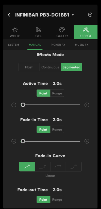
Figure 1.2.3.-3 Segmented Mode
1.2.4 Loop and Manual Effects Status Control Buttons
- Loop is the effect cycle time. The adjustable range is 1 - 100 times, or set to Random. The buttons
 and
and  decide whether the effect performs only 1 cycle for 1 time or if the cycle runs repeatedly. For example, if the loop time is set to 10 and loop once, the effect will play 10 times. If the loop time is set to 10 and loop always, the effect plays for 10 times, then plays another 10 times.
 - Manual effect status control buttons. The 3 status's for manual effects are Running, Paused and Stopped. After setting the effects parameters, tap the
 to play the effect and the status changes to Running. Tap the
  to pause the effect and the status changes to Paused. Tap the
  to stop the effect and the status changes to Stopped.
1.2.5 Manual FX Presets
On the Manual FX page, tap the cube in the top right corner to enter the Presets interface. Tap "Save to Presets" to save the current manual effect to the presets. The saved Manual FX saves to the "EFFECT" section of the Presets. Select the saved Manual FX, then click "OK" to apply it to the fixture.
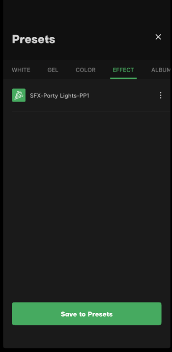
Figure 1.2.3 Save a Manual FX to Presets
2. Picker FX®
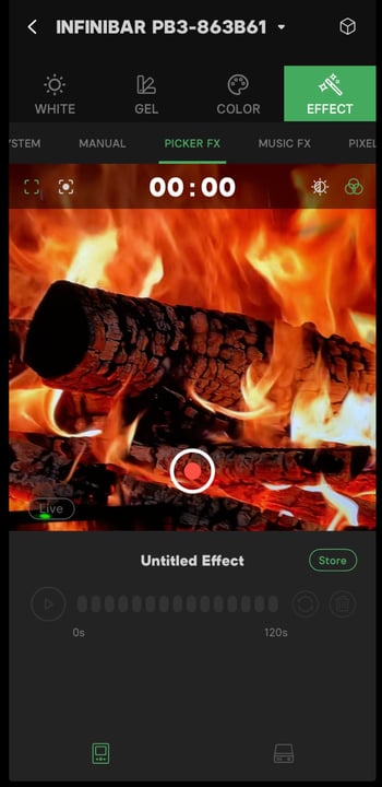
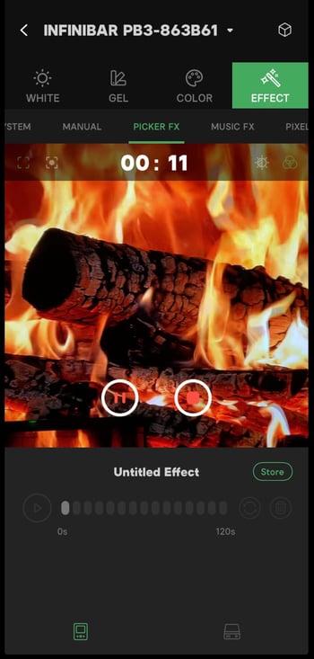
Picker FX® has Recording mode and Live mode. With the camera on the smart device, users can record real-life effects with the camera on the smart device and apply them to fixtures. After recording the effects, users can adjust the HUE and SAT. Users can apply the recorded effects to fixtures.
Note:
Maximum 10 custom lighting effects (C-FX) for one fixture.
|
|
| Figure 2-1 Picker FX Interface | Figure 2-2 Picker FX Live |
2.1 Recording Mode
2.1.1 Record Video in Recording Mode
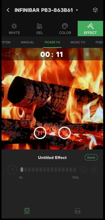
- In Recording mode, tap the
 button to start recording video. The maximum recording time is 120 seconds.
 - Users can select the source base and the metering mode before starting the recording. The source base contains HSI mode
 and CCT mode
  . The Metering mode contains spot mode and evaluative mode.
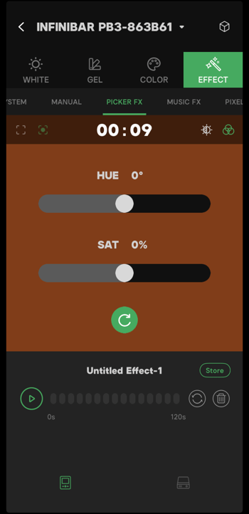
 - When recording is complete, tap "preview" on the pop-up window. The recorded effect runs on the fixture. Users can preview the lighting effects and adjust the HUE and SAT. HUE adjustable range is -120° to +120°; SAT adjustable rang is -30° to +30°.
- Tap the green
 button to restart the Picker FX®.
 - Tap
 to play the recorded effect on the fixture. Tap
  to set the cycle mode for the effect.
  cycles once, cycles infinitely.
 - Tap
 to delete the current effect.
|
|
| Figure 2.1.1-1 Record in Recording Mode | Figure 2.1.1-2 Recording Finished |
2.1.2 Store the Recorded Effects
- After recording the effect, tap "OK" on the pop-up window to save the recorded effect to the store.
- Tap "Store" on the right to view saved effects.
- The user can rename, manage the store and delete effects in the store.
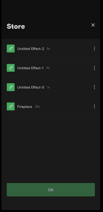
Figure 2.1.2-1 Picker FX Store
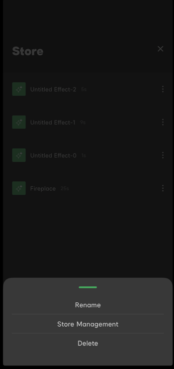
Figure 2.1.2-1 Picker FX Store Options
2.1.3 Upload the Recorded Effects to the Fixture
- Save the effect to the store before uploading it to the fixture.
- Tap
 to enter the effects uploading page. The ten blanks on the uploading page are in the order of the ten save spaces in the fixture. Select a blank then tap
  to open the effects store, then select the effect to upload.
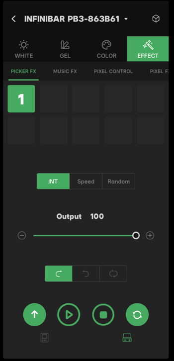
Figure 2.1.3 Upload a Saved Effect to the Fixture
2.1.4 Play the Uploaded Effects
- The user can play the uploaded effects via Sidus Link® and adjust the play mode.
- INT: Change the effects intensity while playing the effect. The adjustable range is 0 - 100.
- Speed: Change the effect play speed when playing the effect. The adjustable range is 0.5X - 16X.
- Random: Change the effects play order.
- Effect Play Order:
 plays the effect in the positive order.
  plays the effect in the reverse order.
  is an infinite loop. Tap it to change the loop time.
 - The control button:
 to play effect, tap again to pause the effect.
  Tap to stop the current effect.
  plays the effect in loop mode. Tap to switch it to play once mode
  .
.
Note:
- The source base limits the lighting effects performance on different fixtures. For example, if the source base is CCT mode, it remains in CCT mode even when applied to RGB fixtures.
- Fixtures with a display can play lighting effects without app control.
2.2 Live Mode
- In Live mode, tap the bottom right corner
 to enter the HUE and SAT adjustment menu. The HUE adjustable range is -120° - 120°. The SAT adjustable range is -30% - 30%. Click
  again to close the HUE and SAT adjustment menu.
 - The display bar under the camera interface
 is representing the real-time intensity percentage and HUE.
 - The INT slider adjusts the live effect's intensity. The adjustable range is 0.1X to 10X.
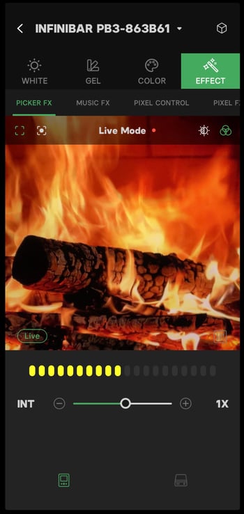
Figure 2.2 Live Mode
Note:
The fixture ability limits the performance quality of the effect.
3. Magic Program™ Go
Magic Program™ Go is the upgraded lighting effect editing and programming tool with various layout shapes and lighting effect templates built in. The user could customize and run a lighting program using the built-in layout shapes and lighting effect templates. Magic Program™ Go supports a connection to a maximum of 25 fixtures.
3.1 Entering Magic Program™ Go
At the project main menu, click the Magic Program™ button  at the bottom of the screen to enter Magic Program™. The default mode when you enter is Magic Program™ Go.
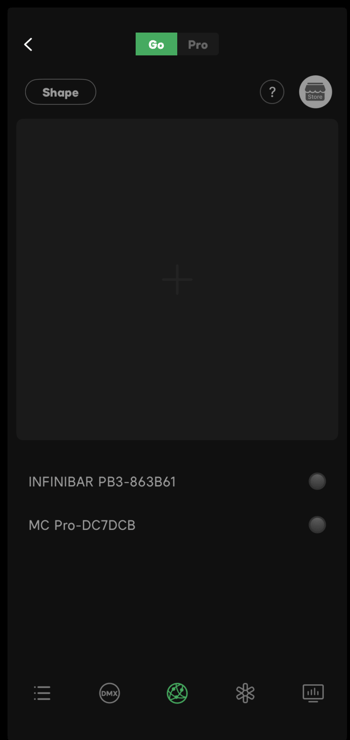
Figure 3.1-1 Magic Program™ Go
- Tap the Layout Shape button
 or Add New Layout button
  to choose a new layout shape. Details see Layout Shape.
 - Tap the Store button
 to use and manage saved effects. Details see Store.
 - Fixtures that are connected to the project will be listed at the bottom of the interface. Use the fixture locate button
 to locate the fixture. When the fixture locate button is tapped, the fixture will flash.
 - Quick Guide: to improve user experience, Magic Program™ Go provides Quick Guide function. Tap the Quick Guide icon
 to view descriptions of buttons in this interface. If you need to close the Quick Guide, tap somewhere else or tap the Quick Guide icon again.
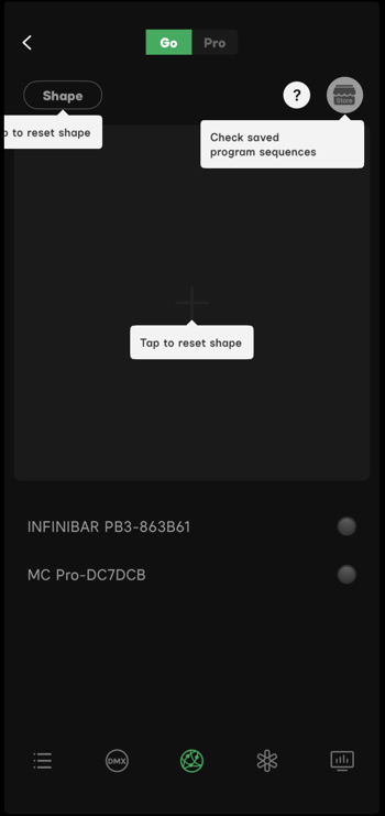
Figure 3.1-2 Quick Guide
Note:
Fixtures that don't support Magic Program™ cannot be added to the layout. There will be a  next to the fixture.
3.2 Layout Shape
Magic Program™ Go has 8 built-in layout shapes, including Matrix, Rectangle, Circle, Doughnut, Triangle, Hexagon, Pentastar, X-shaped and custom shape.
- Tap Layout Shape button or Add New Layout button
 to choose a new layout shape.
 - Tap any shape to enter the setup interface.
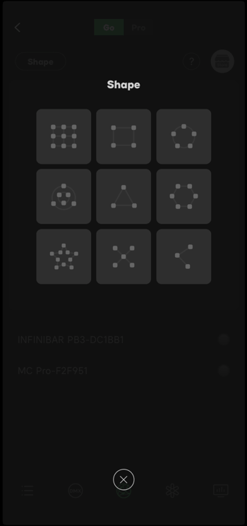
Figure 3.2-1 Layout Shape Choices
- Each layout shape can be applied to a maximum of 25 fixtures.
- If a large number of fixtures are connected, tap the Zoom In button
 to enlarge the view. If you need to restore the default view, tap the Zoom Out button
  .
. - The app will detect the most suitable ratio of view when configuring the layout shape.
- Because the maximum number of light fixtures that can be connected is 25, the system will adjust the number of one parameter based on the other related parameters.
- While setting up a layout shape, tap the Layout Shape button again to view all 9 shape choices. Taping any of the choices will reset the current setup. A window will popup for confirmation. After confirming the reset, the current setup will not be able to be restored.
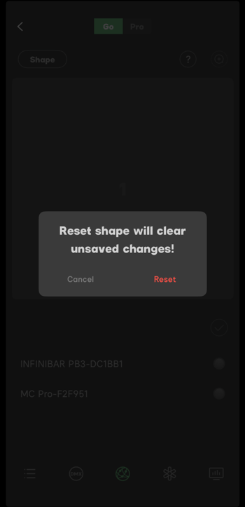
Figure 3.2-2 Reset Confirmation
3.2.1 Matrix
- Tap the Matrix button
 to enter the setup interface for the Matrix layout.
 - In Matrix setup, adjust the sliders to set the values of x and y, or use the plus
 and minus
  buttons. After setting the number of fixtures, tap Confirm.
 - Tap the target fixture in the fixture list, then tap a location number to link. The linked number will light up. If you need to remove the link, tap the number again to unlink.
- After linking the fixtures with location numbers, tap confirm
 to enter Go Program Interface.
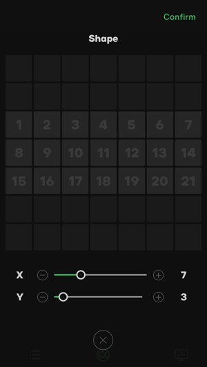
Figure 3.2.1-1 Set Number of Fixtures
3.2.2 Rectangle
- Tap the Rectangle button
 to enter the setup interface for the Rectangle layout.
 - In Rectangle setup, adjust the sliders to set the values of x and y, or use the plus and minus buttons. After setting the number of fixtures, tap Confirm.
- Tap the target fixture in the fixture list, then tap a location number to link. The linked number will light up. If you need to remove the link, tap the number again to unlink.
- After linking the light fixtures with location numbers, tap confirm to enter Go Program Interface.
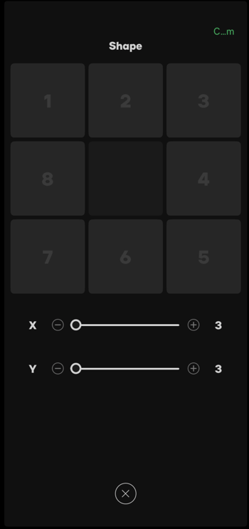
Figure 3.2.2 Set Number of Fixtures
Note:
- The minimum number for X and Y is 3.
- The numbers in the Rectangle layout will be populate clockwise.
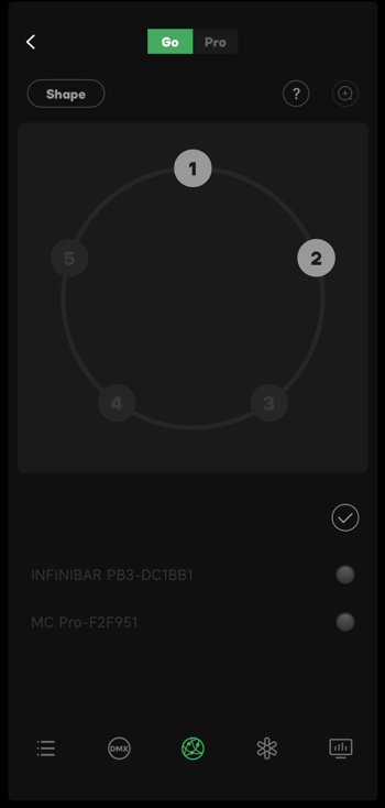
3.2.3 Circle
- Tap the Circle button to enter the setup interface for the Circle layout.
- In Circle setup, adjust the sliders to set the values of x and y, or use the plus and minus buttons. After setting the number of fixtures, tap Confirm.
- Tap the target fixture in the fixture list, then tap a location number to link. The linked number will light up. If you need to remove the link, tap the number again to unlink.
- After linking the light fixtures with location numbers, tap confirm to enter Go Program Interface.
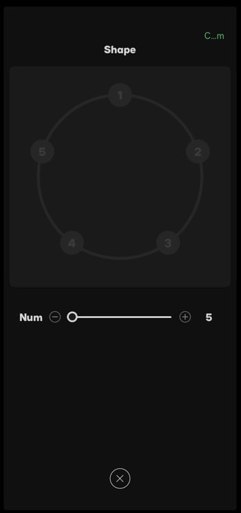
|
|
| Figure 3.2.3-1 Set Number of Fixtures in the Rectangle Layout | Figure 3.2.3-2 Link Fixture with a Location |
Note:
- For the best performance, the Circle layout supports a range of 5 - 25 linked fixtures.
- The numbers in the Circle layout will be populated in clockwise order.
3.2.4 Doughnut
- Tap the Doughnut button
 to enter the setup interface for the Doughnut layout.
 - In Doughnut setup, there are two modes: Solid
 and Hollow
  . Solid Mode means a circle layout with a center. Hollow Mode means a circle layout without a center.
 - Adjust the In slider
 to choose the number of fixtures on the inner circle. Adjust the Out slider
  to choose the number of fixtures on the outer circle, or use the plus and minus buttons. After setting the number of fixtures, tap Confirm.
 - Tap the target fixture in the fixture list, then tap a location number to link. The linked number will light up. If you need to remove the link, tap the number again to unlink.
- After linking the light fixtures with location numbers, tap confirm to enter Go Program Interface.
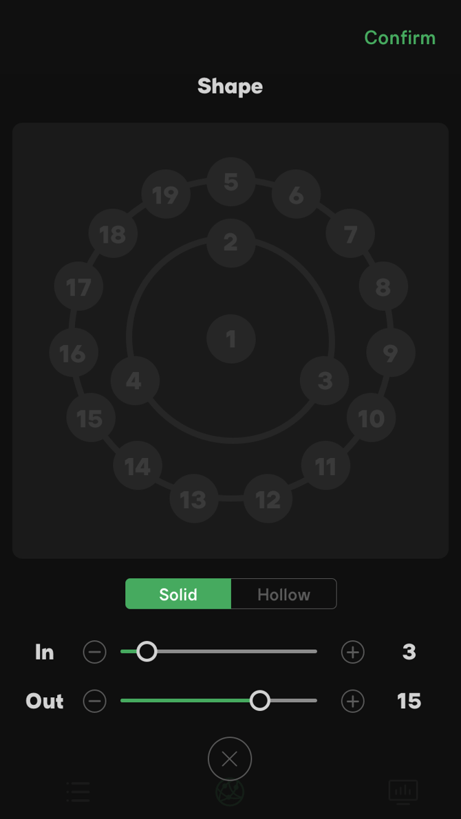 |
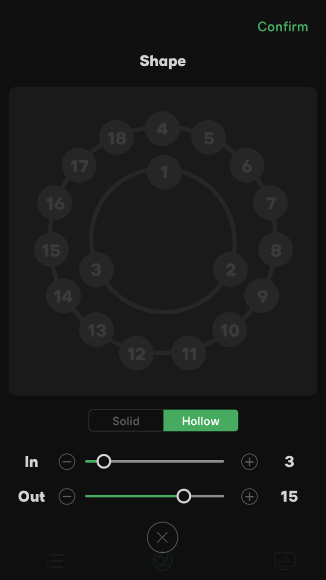 |
| Figure 3.2.4-1 Solid Mode | Figure 3.2.4-2 Hollow Mode |
Note:
- For the best performance, the inner circle supports a range of 3 - 10 linked fixtures. The outer circle supports a range of 0 - 14 linked fixtures. The sum of two circles cannot be over 25.
- In Solid Mode, the locations in the Doughnut layout will start in the center, then in clockwise order. In Hollow Mode, the locations will be populated in clockwise order.
3.2.5 Triangle
- Tap the Triangle button
 to enter the setup interface for the Triangle layout;
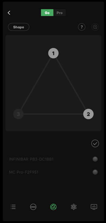
 - In Triangle setup, adjust the slider to choose the number of fixtures. Use the Plus and Minus buttons to choose the number of fixtures by 3 at each time. After setting the number of fixtures, tap Confirm.
- Tap the target fixture in the fixture list, then tap a location number to link. The linked number will light up. If you need to remove the link, tap the number again to unlink.
- After linking the light fixtures with location numbers, tap confirm to enter Go Program Interface.
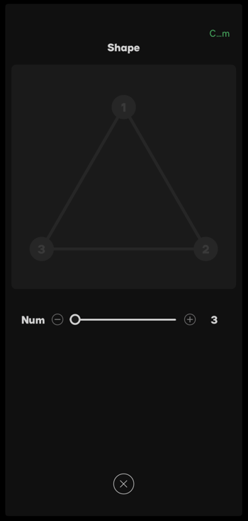
|
|
| Figure 3.2.5-1 Set Number of Fixtures in the Triangle Layout | Figure 3.2.5-2 Link Fixture with a Location |
Note:
- The numbers in the Triangle layout will start with the upper center, then populate clockwise.
- This is an equilateral triangle, so the number of fixtures will be adjusted by 3 at a time.
3.2.6 Hexagon
- Tap the Hexagon button to enter the setup interface for the Hexagon layout.
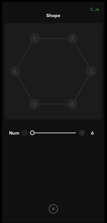
- In Hexagon setup, adjust the slider to choose the number of fixtures. Use the Plus and Minus buttons to choose the number of fixtures by 6 at each time. After choosing the number of fixtures, tap Confirm.
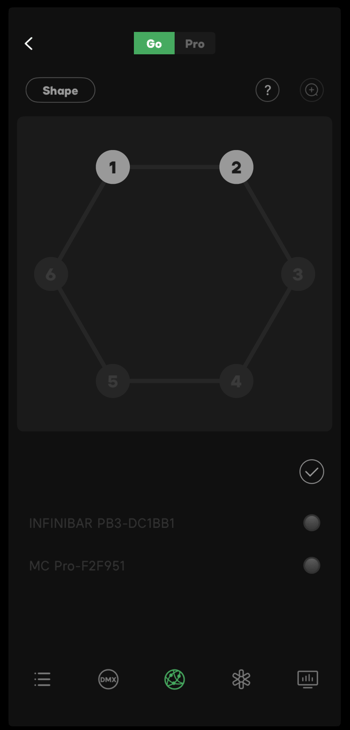
- Tap the target fixture in the fixture list, then tap a location number to link. The linked number will light up. If you need to remove the link, tap the number again to unlink.
- After linking the light fixtures with location numbers, tap confirm to enter Go Program Interface.
|
|
| Figure 3.2.6-1 Set Number of Fixtures for Hexagon Layout | Figure 3.2.6-2 Link Fixtures with a Location |
Note:
The numbers in the Hexagon layout will start with the upper-left corner and then go clockwise.
This is an equilateral hexagon, so the number of fixtures will be adjusted by 6 at each time.
3.2.7 Pentastar
- Tap the Pentastar button
 to enter the setup interface for the Pentastar layout.
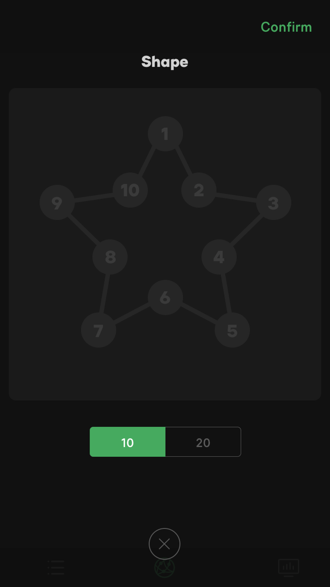
 - In Pentastar setup, there are two modes: 10-fixture Pentastar and 20-fixture Pentastar. After choosing a mode, tap Confirm.
- Tap the target fixture in the fixture list, then tap a location number to link. The linked number will light up. If you need to remove the link, tap the number again to unlink.
- After linking the light fixtures with location numbers, tap confirm to enter Go Program Interface.
 |
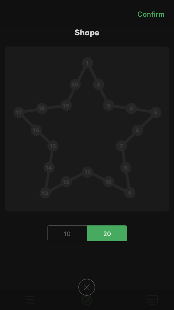 |
| Figure 3.2.7-1 10-fixture Pentastar | Figure 3.2.7-2 20-fixture Pentastar |
Note:
- Because the maximum number of linked fixtures is 25, there are only 10-fixture Pentastar and 20-fixture Pentastar options.
- The numbers in the Pentastar layout will start with the upper corner and then go clockwise.
3.2.8 X-Shape
- Tap the X-Shape button
 to enter the setup interface for the X-Shape layout;
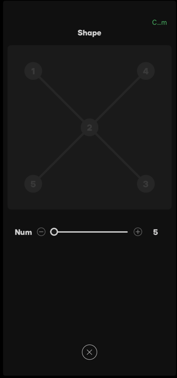
 - In X-Shape setup, adjust the slider to chose the number of fixtures. Use the Plus and Minus buttons to choose the number of fixtures by 4 at each time. After setting the number of fixtures, tap Confirm.
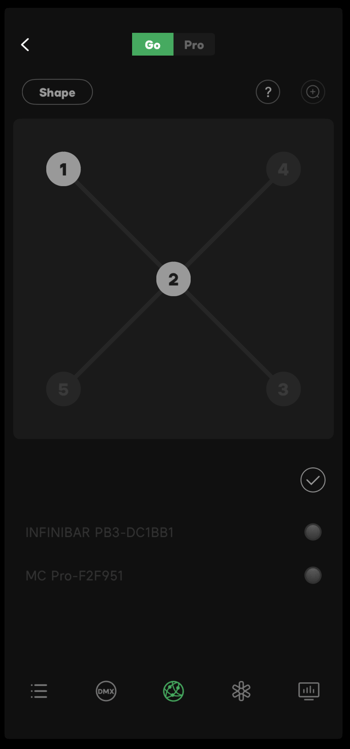
- Tap the target fixture in the fixture list, then tap a location number to link. The linked number will light up. If you need to remove the link, tap the number again to unlink.
- After linking the light fixtures with location numbers, tap confirm to enter Go Program Interface.
|
|
| Figure 3.2.8-1 Set Number of Fixtures for X Layout | Figure 3.2.8-2 Link Fixtures with a Location |
Note:
The numbers in the X-Shape layout will locate in order from upper-left to lower right, upper-right to lower-left;
The minimum number of linked fixtures in the X-Shape layout is 5.
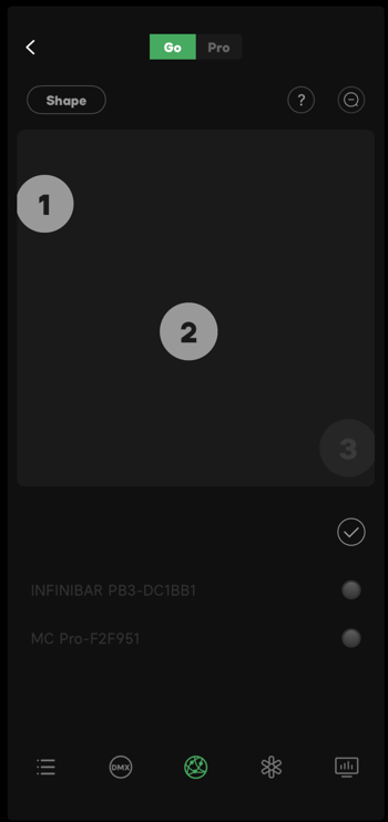
3.2.9 Custom Shape
- Tap the Custom button
 to enter the setup interface for the Custom shape layout.
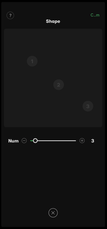
 - In the Custom shape setup, adjust the slider to chose the number of fixtures. Use the Plus and Minus buttons to choose the number of fixtures (location of number is generated randomly).
- Tap any blank space in the layout area to put a fixture there. After setting the number of light fixtures, tap Confirm.
- Tap the target fixture in the fixture list, then tap a location number to link. The linked number will light up. If you need to remove the link, tap the number again to unlink.
- After linking the light fixtures with location numbers, tap confirm to enter Go Program Interface.
|
|
| Figure 3.2.9-1 Set Number of Fixtures for Custom Layout | Figure 3.2.9-2 Link Fixtures with a Location |
3.3 Go Program Interface
After configuring the layout shape, assigning fixture numbers and linking the fixtures with locations, tap confirm to enter Go Program Interface. The effect can be edited and added to the timeline with this interface.
Tap Add Effect button(icon) to enter the Effect Setting interface. Details see Effect Parameter Menu.
3.3.1 Timeline
Magic Program™ Go and Magic Program™ Pro both use a Timeline as their editing base. The program runs the clips assigned on the timeline.
The Timeline is shown as a 30 minute long timeline in the overall view. In the default view, it will be displayed in 10 second sections.
The time on the Timeline will be displayed in the format of XX:XX.XX / XX:XX.XX(the current time / the total time of all clips).
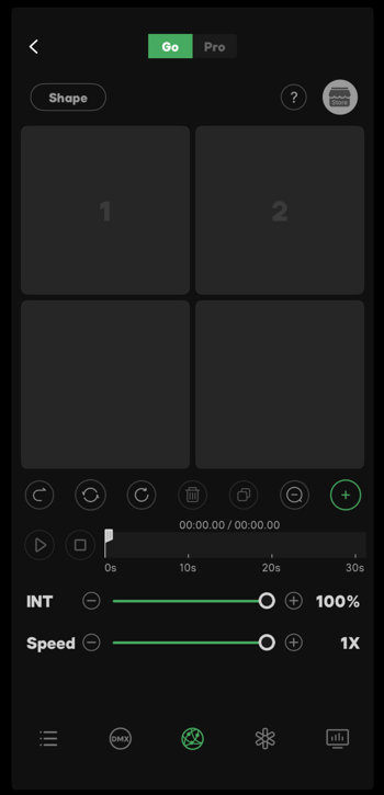
Figure 3.3.1 Timeline
3.3.2 Point Cursor
The Point Cursor  on the timeline indicates the current play location on the timeline. Drag the Point Cursor to anywhere on the timeline.
3.3.3 Effect Clip
The effect clip on the timeline can be flash, pixel chasing or color chasing. The length of each clip is set by the user when adding the clip to the timeline. Different clips will be displayed on the timeline in two different colors.
- Tap to choose a clip then drag to change its location on the timeline.
- Double-tap a clip to enter the Effect Editing interface. Details see Effect Parameter Menu.
- Quickly double-tap a clip to move the point cursor to the beginning of that clip.
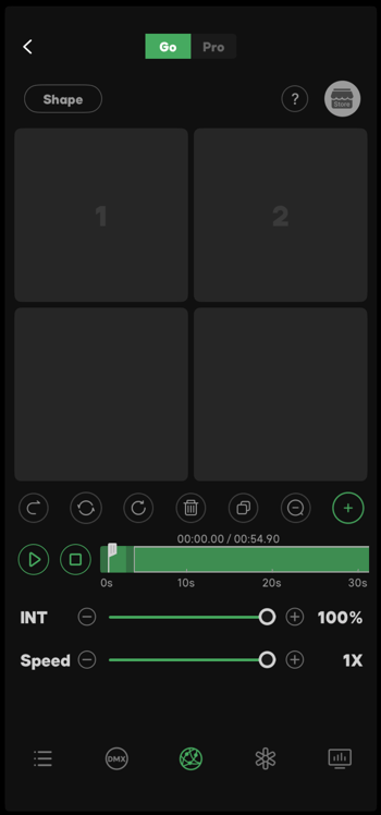
Figure 3.3.3 Effect Clip
3.3.4 INT
- Slide to adjust the INT parameter of all light effect clips on the timeline. The adjustable range is 0 - 100%;
- Use the Plus and Minus buttons to adjust the percentage by 1% at each time.
 Figure 3.3.4 INT
3.3.5 Speed
- Slide to adjust the speed of all effect clips on the timeline. The default adjustable range is 1/8X - 1X.
- The adjustable speed range will automatically adjust to make sure the length of the clip after adjusting will not exceed 30 minutes.
- You can also use the Plus and Minus buttons to adjust the speed.
 Figure 3.3.5 Speed
3.3.6 Store
In the Magic Program™ Go and the Go Program interfaces, tap the Store icon to enter the store interface.
The Store has the following functions:
- View saved Common Effects and Project Effects in the Store and apply the saved effects to the current project.
- Save the current effect to the Store.
- Manage saved Common and Project Effects(rename, delete).
Common Effect: Effects saved from other projects that can be applied to any project that is using the same layout shape.
Project Effect: Effects saved from the current project and can only be used within the current project.
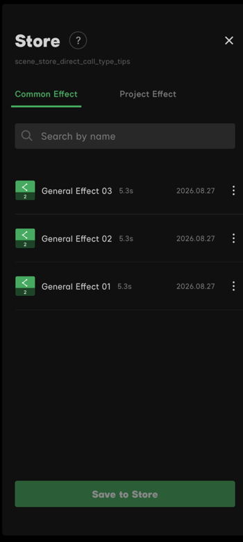
Figure 3.3.6 Store
3.3.7 Function Buttons
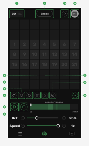 Figure 3.3.7 Go Program Interface Functional Button
- Go/Pro Mode Button
- Shape Button
- Sequential/Reverse Button
- Once/Loop Button
- Timeline Reset Button
- Effect Delete Button
- Play/Pause Button
- Stop Button
- Effect Copy Button
- Timeline Zoom In/Out Button
- Add New Effect Button
- Store Button
- Quick Guide Button
3.3.7.1 Go/Pro Mode Button
Tap Go to change to Magic Program™ Go mode.
Tap Pro to change to Magic Program™ Pro mode.
3.3.7.2 Shape Button
Tap the Layout Shape button to view all 9 layout shapes. Tapping any of the choices will reset the current setup. A window will popup for confirmation. After confirming the reset, the current setup will not be able to be restored.
3.3.7.3 Sequential/Reverse Button
Tap the Sequential/Reverse Button to change the play order of the effect clips on the timeline.
-
 means the timeline will play the effects in forward order.
 -
 means the timeline will play the effects in reverse order.
Note:
This button cannot be used while clips are being played.
3.3.7.4 Once/Loop Button
Tap the Once/Loop Button to change the play cycle mode.
- Once Button:
 The timeline will play the clips once.
 - Loop Button:
 The timeline will play the clips in a loop. After each play cycle, the Point Cursor will return to the beginning of the timeline.
3.3.7.5 Timeline Reset Button
Tap the Timeline Reset Button  to reset the timeline. All of the effect clips on the timeline will be deleted.
Note:
This button cannot be used while clips are being played.
3.3.7.6 Effect Delete Button
Tap to choose any clip from the timeline, then tap the Effect Delete Button  to delete the chosen effect clip.
3.3.7.7 Play/Pause Button
Tap the Play Button  to play the current effect clips on the timeline. The icon will change to the Pause Button
  during playback. Tap the Pause Button to pause the playback.
Note:
If there is no clip on the timeline, the Play/Pause Button is unusable.
3.3.7.8 Stop Button
Tap the Stop button  to stop playing the clips on the timeline. The point cursor will return to the beginning of the timeline.
Note:
If there is no clip on the timeline, the Stop Button is unusable.
3.3.7.9 Effect Copy Button
Tap to choose any clip from the timeline, then tap the Effect Copy Button  to copy the chosen effect clip. The duplicated effect will be placed on the timeline after the original clip.
3.3.7.10 Timeline Zoom In/Out Button
- Use the Timeline Zoom Out button
 to zoom out the view to see the whole 30-minute timeline.
 - Use the Timeline Zoom In button
 to restore the default view.
3.3.7.11 Add New Effect Button
Tap the Add New Effect button  to enter the Effect Parameter Menu. You can edit a new effect clip in Effect Parameter Menu, then add it to the timeline. Details see Effect Parameter Menu.
3.3.7.12 Store Button
Tap the Store button to enter the store menu. You can save the current effect clips to the Store, view saved Common and Project Effects, and apply the saved effects to the current project. Details see Store.
3.3.7.13 Quick Guide Button
Tap the Quick Guide button to view descriptions of some elements of the interface. If you need to close the Quick Guide, tap somewhere else or tap the Quick Guide button again.
3.4 Effect Parameter Menu
In the Go Program Interface, tap the Add New Effect button to enter the Effect Parameter Menu. Magic Program™ Go has 3 light effect templates, including Flash, Pixel Chasing and Color Chasing. The default template is Flash when you enter the Effect Parameter Menu. Slide the window to view the other two templates. You can customize the parameters of the effects, then preview the effect in the preview window.
3.4.1 Source Base
In Flash, Pixel Chasing and Color Chasing, tap the Source Base button  to enter the Source Base interface.
- Tap CCT
 to change to the CCT menu.
 - Tap HSI
 to change to the HSI menu.
3.4.1.1 CCT
There are two CCT modes, the Point Mode and Range Mode . In Point Mode, the user can set a fixed value for CCT. In Range Mode, the user can set a color range for the CCT parameter. The parameter changes along with the selected chase mode, within the selected range.
- Point: Adjust the slider to set a fixed value for CCT. All connected fixtures in this scene will remain the same value.
- Range: Adjust the sliders to set a color range for CCT. Range Mode has 4 chase modes, including, Sequential, Reverse, Alternating and Random modes.
Range Chase Mode:
- Sequential: CCT parameter varies from the minimum value to the maximum value within the selected range.
- Reverse: CCT parameter varies from the maximum value to the minimum value within the selected range.
- Alternating: CCT parameter varies from the maximum value to the minimum value and then back from the minimum value to the maximum value within the selected range.
- Random: CCT parameter varies with random values within the selected range.
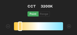 Figure 3.4.1.1-1 CCT Point Mode
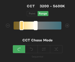 Figure 3.4.1.1-2 CCT Range Mode
3.4.1.2 G/M
There are two G/M modes: Point Mode and Range Mode . In Point Mode, the user can set a fixed value for G/M. In Range Mode, the user can set a range for the G/M parameter. The parameter will vary in the selected chase mode, within the selected range.
- Point: Adjust the slider to set a fixed value for G/M. All connected fixtures in this scene will remain the same value.
- Range: Adjust the sliders to set a range for G/M. Range Mode has 4 chase modes, including, Sequential, Reverse, Alternating and Random modes.
Range Chase Mode:
- Sequential: G/M parameter varies from the minimum value to the maximum value within the selected range.
- Reverse: G/M parameter varies from the maximum value to the minimum value within the selected range.
- Alternating: G/M parameter varies from the maximum value to the minimum value and then back from the minimum value to the maximum value within the selected range.
- Random: G/M parameter varies with random values within the selected range.
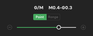 Figure 3.4.1.2-1 G/M Point Mode
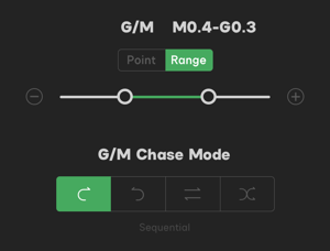 Figure 3.4.1.2-1 G/M Range Mode
Note:
The connected fixture must support the G/M adjustment to be able to use this function in the app.
3.4.1.3 HSI-HUE
Tap HSI to change to the HSI menu. You can adjust the HUE parameter here.
There are two HUE modes: Point Mode and Range Mode . In Point Mode, the user can set a fixed value for HUE. In Range Mode, the user can set a range for the HUE parameter. The parameter changes along with the selected chase mode, within the selected range.
- Point: Adjust the slider to set a fixed value for HUE. All connected fixtures in this project will remain the same value.
- Range: Adjust the sliders to set a range for HUE. Range Mode has 4 chase modes, including, Sequential, Reverse, Alternating and Random modes.
Range Chase Mode:
- Sequential: HUE parameter varies from the minimum value to the maximum value within the selected range.
- Reverse: HUE parameter varies from the maximum value to the minimum value within the selected range.
- Alternating: HUE parameter varies from the maximum value to the minimum value and then back from the minimum value to the maximum value within the selected range.
- Random: HUE parameter varies with random values within the selected range.
3.4.1.4 HSI-SAT
Tap HSI to change to the HSI menu. You can adjust SAT parameter here.
There are two SAT modes: Point Mode and Range Mode . In Point Mode, the user can set a fixed value for SAT. In Range Mode, the user can set a range for the SAT parameter. The parameter changes along with the selected chase mode, within the selected range.
- Point: Adjust the slider to set a fixed value for SAT. All connected fixtures in this project will remain the same value.
- Range: Adjust the sliders to set a range for SAT. Range Mode has 4 chase modes, including, Sequential, Reverse, Alternating and Random modes.
Range Chase Mode:
- Sequential: SAT parameter varies from the minimum value to the maximum value within the selected range.
- Reverse: SAT parameter varies from the maximum value to the minimum value within the selected range.
- Alternating: SAT parameter varies from the maximum value to the minimum value and then back from the minimum value to the maximum value within the selected range.
- Random: SAT parameter varies with random values within the selected range.
3.4.2 Flash
The default effect template is Flash when you enter the Effect Parameter Menu. You can customize all parameters of the flash effect, then preview the effect in the preview window.
3.4.2.1 INT
There are two INT modes: Point Mode and Range Mode . In Point Mode, the user can set a fixed value for INT. In Range Mode, the user can set a range for the INT parameter. The parameter changes along with the selected chase mode, within the selected range.
- Point: Adjust the slider to set a fixed value for INT. All connected fixtures in this project will remain the same value.
- Range: Adjust the sliders to set a range for INT. Range Mode has 4 chase modes, including, Sequential, Reverse, Alternating and Random modes.
Range Chase Mode:
- Sequential: INT parameter varies from the minimum value to the maximum value within the selected range.
- Reverse: INT parameter varies from the maximum value to the minimum value within the selected range.
- Alternating: INT parameter varies from the maximum value to the minimum value and then back from the minimum value to the maximum value within the selected range.
- Random: INT parameter varies with random values within the selected range.
 Figure 3.4.2.1-1 INT Point Mode
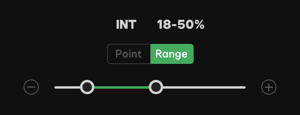 Figure 3.4.2.1-2 INT Range Mode
3.4.2.2 Speed
The range of the Speed parameter is between 200ms - 1600ms. The Speed parameter indicates the time between the linked fixture's flashes. 200ms is the fastest, 1600ms is the slowest.
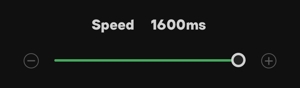 Figure 3.4.2.2 Speed
3.4.2.3 FRQ
The range of the Frequency parameter is from 0.1Hz - 1Hz - 10Hz. The Frequency parameter indicates the frequency of linked fixtures's flashes. Lower Hertz values create a slower frequency. Higher Hertz values create a faster frequency.
 Figure 3.4.2.3 Frequency
3.4.2.4 Time
The range of the Time parameter is 1 - 10. The Time parameter indicates the number of flashes each fixture will perform in the current effect.
 Figure 3.4.2.4 Time
3.4.2.5 Loop
The range of the Loop parameter is 1 - 99. The Loop parameter indicates the number of loops the effect will be played when it is added to the timeline.
 Figure 3.4.2.5 Loop
3.4.3 Pixel Chasing
Slide the window to change to the Pixel Chasing template. You can customize all parameters of the effect, then preview the effect in the preview window.
3.4.3.1 Splice/General
There are two connection modes in Pixel Chasing:
- Tap the Splice button
 to change to Splice mode.
 - Tap the General button
 to change to General mode.
Splice: Colors moves as a whole between lights. There is only a small difference between lights.
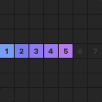 Figure 3.4.3.1-1 Splice
General: Colors chase between lights. The differences between colors will be displayed as chasing each other. There is an obvious difference between lights.
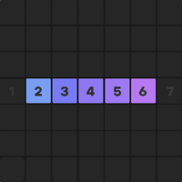 Figure 3.4.3.1-2 General
3.4.3.2 INT
The adjustable range for INT is 0 - 100%. The INT parameter indicates this brightness of the fixture.
 Figure 3.4.3.2 INT
3.4.3.3 Speed
The range of the Speed parameter is from 200ms - 1600ms. The Speed parameter indicates the time between the two adjacent light fixture's flashes. 200ms is the fastest, 1600ms is the slowest.
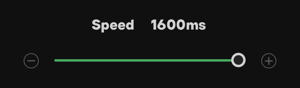 Figure 3.4.3.3 Speed
3.4.3.4 Pixel
The range of the Pixel parameter is from 1 to the number of linked fixtures. The Pixel parameter indicates the number of fixtures running in the chase effect.
For the best pixel chasing effect, the maximum number of pixels must be one less than the number of connected fixtures in this scene.
 Figure 3.4.3.4 Pixel
3.4.3.5 Loop
The range of the Loop parameter is from 1 - 99. The Loop parameter indicates the number of loops the effect will be played when it is added to the timeline.
 Figure 3.4.3.5 Loop
3.4.4 Color Chasing
Slide the window to change to the Color Chasing template. You can customize all parameters of the effect, then preview the effect in the preview window.
There are two connection modes in Color Chasing:
- Tap the Splice button to change to Splice mode.
- Tap the General button to change to General mode.
Splice: Colors move as a whole between fixtures. There is only a small difference between the fixtures.
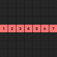 Figure 3.4.4-1 Splice
General: Colors chase between fixtures. The differences between colors will be displayed as chasing each other. There is an obvious difference between the fixtures.
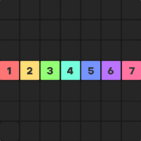 Figure 3.4.4-2 General
3.4.4.1 INT
The adjustable range for INT is 0 - 100%. The INT parameter indicates this brightness of the fixture.
 Figure 3.4.4.1 INT
3.4.4.2 Speed
The range of the Speed parameter is from 200ms - 1600ms. The Speed parameter indicates the time between the connected fixture's flashes. 200ms is the fastest. 1600ms is the slowest.
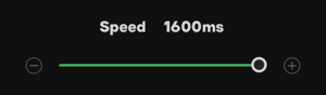 Figure 3.4.4.2 Speed
3.4.4.3 Loop
The range of the Loop parameter is from 1 - 99. The Loop parameter indicates the number of loops the effect will be played when it is added to the timeline.
 Figure 3.4.4.3 Loop
3.4.5 Preview Window
The Preview Window in the Effect Parameter Menu will display the light effect with current parameter settings.
3.4.6 Time
The time on the Timeline will be displayed in the format of XX:XX.XX / XX:XX.XX(the current time / the total time of all clips).
Note:
The length of the effect clip must be shorter than the length of time left on the timeline, otherwise, the current effect clip cannot be added to the timeline.
3.4.7 Preset
In Flash, Pixel Chasing and Color Chasing, tap the Preset button  to enter Presets. Preset has the following functions:
- View saved effect presets and apply the saved effect presets to current effect being edited.
- Save the current effect to Presets.
- Manage saved effect presets(rename, delete).
Effect Filter:
-
Use the Filter button
 to filter the effects: Flash, Pixel Chasing and Color Chasing.
 - After choosing the target effect, tap somewhere else or tap the Filter button
 again to view the target effect presets.
 - Tap the target effect again to restore the filter to default.
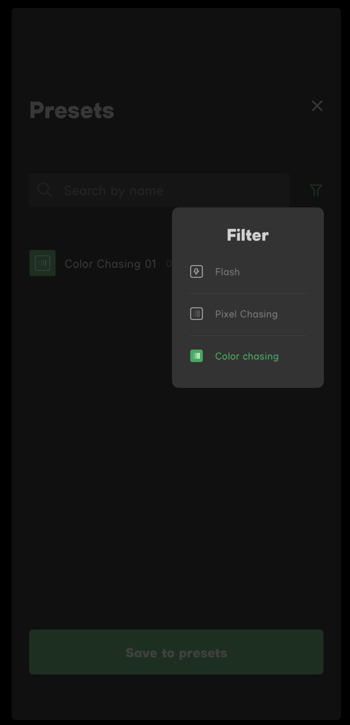
Figure 3.4.7 Presets
3.4.8 Function Buttons
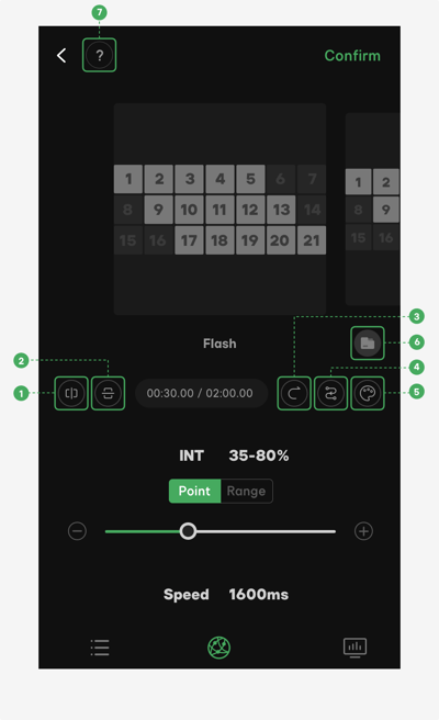 Figure 3.4.8 Function Buttons
- Horizontal Mirror Button
- Vertical Mirror Button
- Sequential/Reverse Button
- Route Setting Button
- Source Base Button
- Preset Button
- Quick Guide Button
3.4.8.1 Horizontal Mirror Button
Horizontal Mirror Button  : The effect of each fixture in the preview window will be mirrored horizontally.
Note:
Custom layout is not symmetrical, therefore it does not support this function.
3.4.8.2 Vertical Mirror Button
Vertical Mirror Button  : The effect of each fixture in the preview window will be mirrored vertically.
Note:
The Circle(if the number is odd), Doughnut(if the number is odd), Triangle, Pentastar and the Custom layouts are not symmetrical vertically, therefore they do not support this function.
3.4.8.3 Sequential/Reverse Button
Tap Sequential/Reverse Button will change the play order of effect clips on the timeline.
- Sequential Button : The timeline will play the clips forward.
- Reverse Button : The timeline will play the clips backward.
3.4.8.4 Route Setting Button
Tap the Route Setting Button  to set the route for the effect.
- The first number you tap in the preview window will be set as the starting point. Tap another number in the preview window will set that number as the finish point.
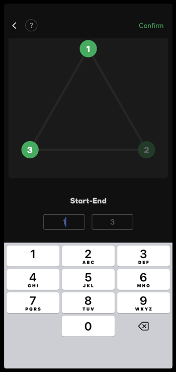
Figure 3.4.8.4 Route Setting
Note:
If the number you are typing into the finish point box is larger than the number of connected fixtures in this scene, the system will change your typed number to the number of connected fixtures in this scene.
3.4.8.5 Source Base Button
Tap the Source Base Button to enter the Source Base interface. By adjusting parameters in this interface, you will create a source base of CCT or HSI for the effect. Details see 3.4.1 Source Base.
3.4.8.6 Preset Button
Tap the Preset button to enter Presets. In Presets, you can save the current light effect, view saved effect presets and manage the saved presets. Details see 3.4.7 Preset.
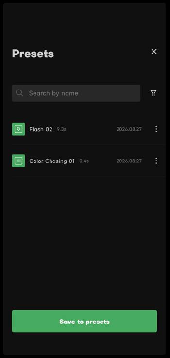
Figure 3.4.8.6 FX Presets
3.4.8.7 Quick Guide Button
Tap the Quick Guide icon to view descriptions of buttons on this interface. If you need to close the Quick Guide, tap somewhere else or tap the Quick Guide icon again.
4. Magic Program™ Pro
Magic Program™ Pro is a lighting editing and programming function. It is based on a timeline, supporting a maximum of 25 fixtures. The user can customize and run a custom lighting program. Connect at least one fixture that supporting Magic Program™, then tap the at the bottom of the scene to enter the Magic Program™ editing interface.
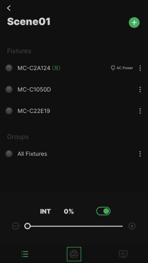 Figure 4 Magic Program™ Icon
Note:
- Users cannot add fixtures that do not support Magic Program™ to the program. There will be a ban
 icon after the fixture.
4.1 Matrix
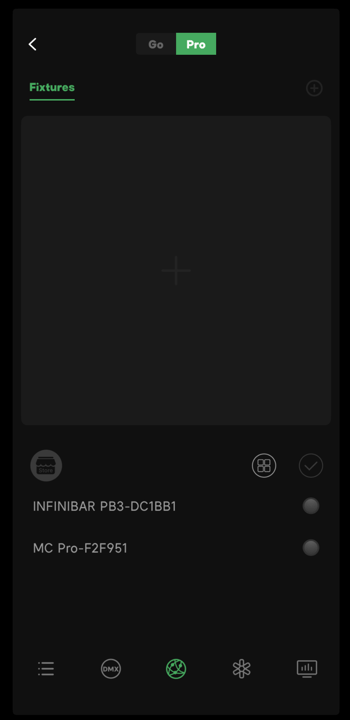
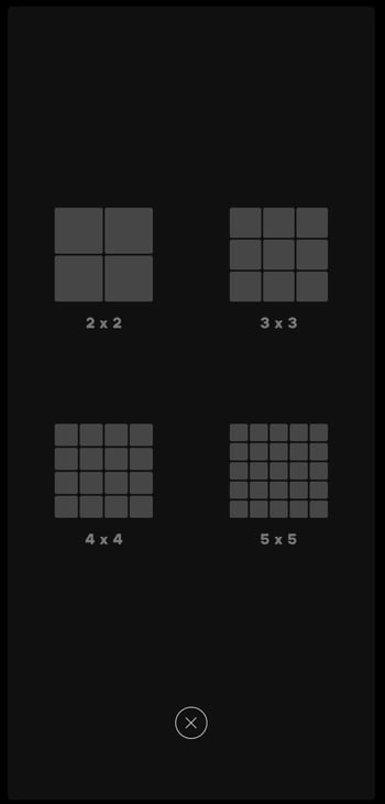
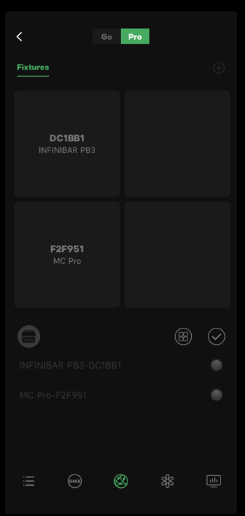
Select and create a Matrix to start the programming. The App supports 2*2, 3*3, 4*4, and 5*5 matrix arrangement. Select the fixture then click the blank in the matrix to add the fixture. A matrix is a group that contains all the fixtures. Based on the matrix, the user could add customised arrays.
|
|
|
| Figure 4.1-1 Magic Program™ Pro interface | Figure 4.1-2 Select the Matrix | Figure 4.1-3 Create a New Matrix |
4.2 Timeline
Timeline is the editing base for Magic Program™ Pro. The program plays along the nodes assigned to the timeline. The editable timeline length is 10 minutes in total. With cycle mode, the actual effects can play longer than 10 minutes.
- Slide the timeline to observe different parts of the program.
- The minimum gap between two nodes is 200ms.
4.2.1 Point Cursor
- The Point Cursor
 on the timeline indicates the current editing location.
 - Double-tap a blank space in the timeline to quickly move the point cursor.
4.2.2 Node
-
A node
 is the minimum editing unit. A single node time length is 0.2 seconds, which means that the minimum time gap in between two lighting effects indication is 0.2 seconds.
 -
The single fixture continuous time is not limited to 0.2 seconds. Users can customize the fixture's continuous time. (In the iPad version, the last node on the timeline indicates its continuous-time, providing a reference for adding the next node.)
Node Color, Status and Name
 The number on the node represents the number of the fixture in the matrix.
 The combination of a letter and a number on the node indicates that the fixture is in a customized array.
 The color of the node represents the fixture's color or the color temperature. Parts of the color chase effects or color range effects display as a single red node.
- A solid node with a name represents flash and continuous effects. A hollow node with a name
 represents an off fixture. A hollow node without a name
  represents a blank node. A blank node doesn't have an effect.
 - Tap the added node to edit the node's parameters. Users cannot change the selected mode (Flash or continue) for the node, but they can edit the parameters within the selected mode. Users cannot change the related fixture of the added node.
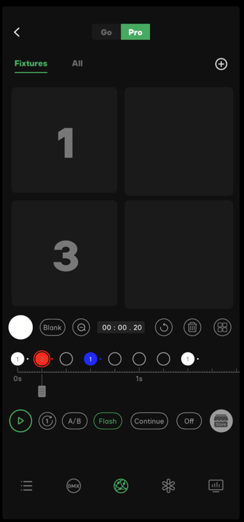
Figure 4.2.2 Node
4.3 Effects Parameter Menu
To quickly edit the node parameters on the timeline, enter the effects parameter menu and set the default parameter for the fixtures.
4.3.1 Flash
To set Flash as the default parameter, click the Flash button  . When the flash button turns green
  , the default parameter is flash mode.
When the flash button is green, click it again to enter the flash mode parameter menu.
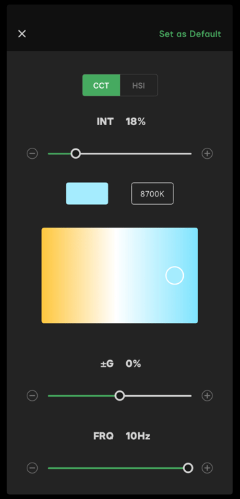
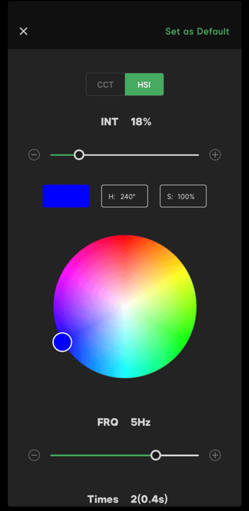
- Source base: CCT and HSI modes.
- In CCT mode, the adjustable range is 1800K - 10000K. The actual color displayed is limited by the fixture's ability. G/M has an adjustable range from M 1.0 - G 1.0.
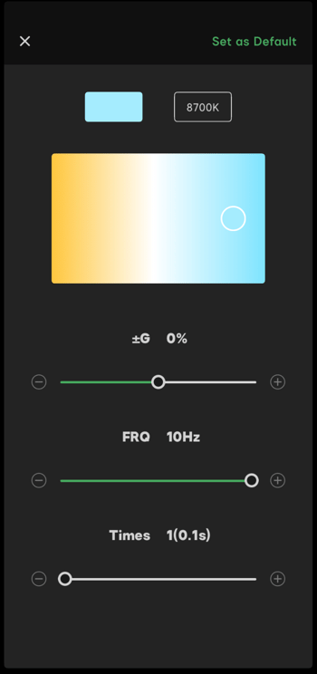
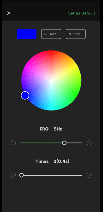
- In HSI mode, the user can choose a color on the color wheel. The actual color displayed is limited by the fixture's ability.
- The FRQ adjustable range is 0.1Hz - 10Hz.
- The flash Times adjustable range is 1(0.1s) - 1000(100.0s), or Always.
Note:
Users can adjust the G/M only when the fixture supports G/M adjustment.
|
|
| Figure 4.3.1-1 Source Base | Figure 4.3.1-2 CCT Mode Parameters |
|
|
| Figure 4.3.1-3 HSI Mode | Figure 4.3.1-4 Parameters in the HSI Mode |
4.3.2 Continue
To set Continue as the default parameter, click the Continue button  to select the Continue mode. When the continue button turns to green
  , the default parameters are in Continue mode. If the user adds a node, the fixture runs along with the Continue mode default parameters. Continue mode default parameters are CCT 5600K (G/M=0), INT 18%, G/M 0, Fade-in Time 0s, Fade-in Curve Linear, Continue Time Always, Fade-out Time 0s, Fade-out curve Linear.
There are 3 sub-modes in Continue mode: Continue, Chase and Effect.
A. Sub-modes for Continue

- Source base: CCT and HSI modes
- In CCT mode, the adjustable range is 1600K - 10000K. The actual color produced is limited by the fixture's ability. G/M adjustable range is M 1.0 to G 1.0.
- In HSI mode, the user can choose a color on the color wheel. The actual color produced is limited by the fixture's ability.
- Fade-in/Fade-out Time has an adjustable range from 0 - 20 seconds.
- The Fade-in/Fade-out Curves are Linear
 , Exponential
  , Logarithmic
  and S-Curve
  .
. - Continue Time has an adjustable range from 0 - 100.0 seconds, or Always.
Note:
Users can adjust the G/M only when the fixture supports G/M adjustment.
B. Sub-mode Chase

- Source base: CCT and HSI modes
- In Point mode, the parameter is a static value, set by the user.
- In Range mode, the parameter is a selected range, set by the user. The actual value varies within the selected range.
- The Chase modes are Sequential, Reverse, Alternating, and Random.
- Sequential: Parameters vary from minimum to maximum within the selected range.
- Reverse: Parameters vary from maximum to minimum within the selected range.
- Alternating: Parameters vary from maximum to minimum and then back from minimum to maximum within the selected range.
- Random: Parameters vary with random values within the selected range.
- CCT mode as source base: The user can set the color temperature, G/M and INT to a point or a range. When selecting Range mode, the user needs to select the INT Chase Mode.
- HSI mode as source base: The user can set the HUE, SAT and INT to a point or a range.
- When selecting Range mode, the user needs to select the Hue Chase Mode.
- The adjustable Time range is 0.1 - 100 seconds.
- Loop modes are Once and Always.
C. Sub-mode Effect
The sub-mode Effect contains 15 types of system effects (The available system effects are limited by the fixture's ability.). The 15 types of system effects are Fireworks, Faulty Bulb, Lighting, TV, Pulsing, Strobe, Club Lights, Candle, Fire, Welding, Cop Car, Color Chase, Party Lights and Paparazzi.
The parameters of the system effects are adjustable. For details see System effects mode.
When the fixtures are playing the effects, the fixture cube in the matrix displays ".FX."
Note:
The presence of Sidus system effects is limited by the fixture ability. If the fixture doesn't support the system effects, Magic Program™ will replace them with compatible effects automatically.
4.4 Function Buttons
.png?width=400&height=669&name=4.4@2x%20(1).png)
Figure 4.4.1 Function Buttons
- Color plate button
- Blank
- Timeline zoom in and zoom out button
- Timeline reset button
- Node delete button
- Create a new matrix button
- Play button
- Once/Loop button
- A/B range cycle button
- Off button
4.4.1 Color Plate Button
The color plate is used to quickly change the source base. Tap the color plate button  to enter the source base menu. The Color plate contains CCT and HSI modes.
4.4.2 Blank
Tap Blank  to add a blank space on the timeline. The blank node has no command. It fills in a space between two commands, which keeps the timeline in order. A user can add a blank node manually. When moving the point cursor to a further location on the timeline and adding a new node, Magic Program™ will add a blank node automatically.
4.4.3 Timeline Zoom In and Zoom Out Button
Tap  and
and  to zoom in and zoom out of the timeline. When zoomed in, the user can select, check every node and edit the parameters. When zoomed out, the user can check the whole timeline, however, the user won't see the nodes; only the point cursor is visible.
4.4.4 Timeline Reset Button
Tap the timeline reset button  to reset the timeline to the default. All of the nodes on the timeline will be deleted.
4.4.5 Node Delete Button
Tap to select a node, then the node delete button  turns on. Then tap the node delete button to delete the selected node. When deleting the selected node, the node behind it will auto-indent.
4.4.6 Create a New Matrix Button
Tap the create new matrix button  to create a new matrix. Users need to re-add the fixtures to the new matrix.
Note:
Please save the current sequence to the Store before creating a new matrix. Creating a new matrix will delete the current sequence.
4.4.7 Play/Pause Button
Add a node to light up the play button  . Click the play button to play the current program. Users can play the program from any node. Tap the same button again to pause the program.
4.4.8 Once/Loop Button
Add a node to turn on the Once/Loop button  . Tap the button to change the cycle mode. When the button displays , tap the button to run the sequence once. When the button displays
  , tap the button to loop the sequence.
4.4.9 A/B Range Cycle Button
Tap the A/B button to turn on  the A/B range cycle button. When the button turns to green
  and the letter A starts flashing, move the point cursor to the beginning of the customized range and tap the button again to set point A. There will be a green A that appears on the timeline. Then the letter B starts flashing, move the point cursor to the end of the customized range and tap the button again to set point B. The timeline in the A/B range appears green, tap the play button to loop the A/B range. After setting the A/B range, the user won't be able to edit the rest of the timeline. Tap the A/B range button again to cancel the A/B range cycle.
4.4.10 Off
Use the Off mode to turn off an active fixture.
Tap the Off button  to turn off the active device. When the off button turns to green, the default node setting is off.
The off default parameters are: Color temperature 5600K, INT 0.
4.5 Array
The array is the fixture group within the current matrix, the linked fixtures in the same array run as a group.
- Create a Magic Program™ matrix that automatically generates an array that contains all the fixtures.
- Click the white
 to create a new array. The array name is in the order of the alphabet. The new array capacity is the same as the matrix. Select fixtures and click
  to link the fixtures.
 - The user can set many links in an array. The links names are in the order of numbers.
- Click
 to Unlink the linked fixtures. Click Cancel to discard the array.
 - The user can create a maximum of 26 arrays. The user cannot delete or modify the array once it is created.
- The node from an array displays with letter and number mixed name. For example
 .
.
.png?width=300&height=534&name=4.5@2x%20(2).png) Figure 4.5 Create a New Array
Figure 4.5 Create a New Array
Note:
If you could not link fixtures to the array, please update the firmware to the latest version and try again.
4.6 Store
The user can save the Magic Program™ sequence to the Store and apply the saved CC program to a sequence.
- Tap the
 store icon to enter the store interface, then save the current Magic Program™ sequence to the Store.
 - You can rename or delete the CC program in the Store.
- Open the Store and select the saved CC program, then tap OK to apply the CC program to your sequence.
.png?width=300&height=534&name=4.6@2x%20(1).png) Figure 4.6 Save the Program to the Store
Figure 4.6 Save the Program to the Store
5. Music FX
Music FX is a new feature of the Sidus Pro® FX family. Import an audio file, then Sidus Link® analyzes the audio clip and transform the music file into lighting effects, allowing the lighting effects to play along with the music rhythm.
5.1 Lighting Effects Visualization Window
- The Lighting Effects Visualization Window is located on the top of the Music FX interface. The wave in the visualization window displays the Hertz and BPM of the audio file.
- The dynamic color cube at the right side of the visualization window changes simultaneously with the lighting fixture.
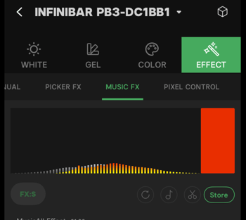
Figure 5.1 Lighting Effects visualization window
5.2 Store Mode, Project Mode and Live Mode
Tap the mode switch button below the visualization window to switch between Store mode, Project mode and Live mode.
5.2.1 Store Mode 
- Users can import audio files with a maximum length of 120 seconds with this mode.
- In Store mode, users can save the effects to the Store and upload them into the fixtures.
Note:
The cloud service does not support automatic cloud saving for Music FX lighting effects.
5.2.2 Project Mode 
- Users can import audio files with a maximum length of 30 minutes with this mode.
- In Project mode, users can save lighting effects to the project store.
Note:
The cloud service does not support automatic cloud saving for Music FX lighting effects.
The lighting effects data in Store mode and Project mode is not interchangeable.
5.2.3 Live Mode 
Tap the play button and the app will start to capture audio via the devices microphone and execute the lighting effects simultaneously.
Note:
Users can adjust lighting parameters and color mapping.
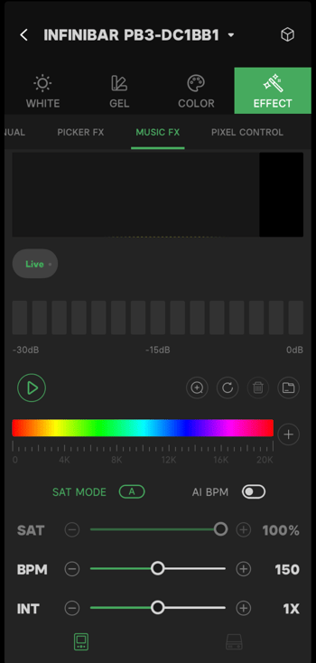
Figure 5.2.3 Music FX Live Mode
5.3 Audio File Clip Editing Timeline
5.3.1 Import Audio Clip
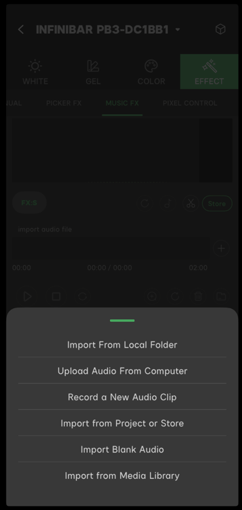
Figure 5.3.1 Import Options
5.3.1.1 Import From Local Folder
- Tap "Import From Local Folder".
- Select the audio file and import it. After the smart analysis, the app will display the audio clip information. Tap the confirm button to complete the file import.
5.3.1.2 Upload Audio From Computer
- Tap "Upload Audio From Computer".
- Visit the website address displayed on the app to enter the audio file transmission page.
- Make sure that the computer and the device are sharing the same Wi-Fi.
- Follow the instructions on the web page, select the audio file from the computer and upload it to the device. Once the device receives the file, the app automatically analyzes the audio clip. The app will display the audio clip information; tap the confirm button to complete the file import.
Note:
- During the audio file submission process, please keep the device screen on. Locking the device will stop the file transmission.
- Sidus Link advises users to submit the audio file via Chrome or Safari browser to maintain transmission stability.
5.3.1.3 Record a New Audio Clip
- Tap "Record a New Audio Clip" to enter the recording interface.
- Tap the recording button to start recording.
- Tap the recording button again to pause the recording.
- Tap the reset button to delete the recorded audio clip.
- Tap the Back button to exit the recording interface.
- Tap the Next button to save the recorded audio. Users can then listen to and edit the recorded audio clip.
- Users can record up to a 30 minute audio clip. The recording will stop automatically once the recording length maximum is reached.
- After recording, tap the next button to analyze the audio clip and check the audio information, then tap the confirm button to finish the file import.
5.3.1.4 Import from Project or Store
- Tap "Import from Project or Store" to enter the Store page.
- Select the saved audio files to import. Users can edit the audio file or modify the color mapping after successfully importing the audio file.
Note:
The app will trim the imported file to fit the current Music FX mode.
5.3.1.5 Import Blank Audio
- Insert a certain length of blank audio to create a gap between two audio clips.
- When playing the blank audio, the lighting fixtures will turn off and not execute any lighting effects.
- Users need to input the Blank time length manually when inserting the blank audio.
- The length of the blank audio is limited by the mode.
5.3.1.6 Import from Media Library
The media library saves all of the imported audio files locally. Users can select and import saved audio files from the media library.
5.3.2 Audio Clip Timeline
The imported audio file automatically loads to the audio clip timeline, users can check the audio clip information and edit the audio clip.
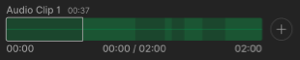
Figure 5.3.2 Audio Clip Timeline
5.3.2.1 Reset the Audio Clip Timeline
Tap the reset button  to reset the current audio clip timeline. The reset will remove the audio clip from the timeline.
5.3.2.2 Audio Clip Information
- Tap the audio clip information button
 to enter the audio clip information page.
 - Tap the zoom in/out button
 to adjust the audio clip timeline display.
 - The effects fade-in and fade-out time adjustable range is 0s - 20s. Tap the reset button to reset the fade-in and fade-out times.
- The default audio hertz mapping range is 0 - 20kHz. The app recommends the hertz mapping range according to the current audio clip. Users can adjust the hertz mapping range manually.
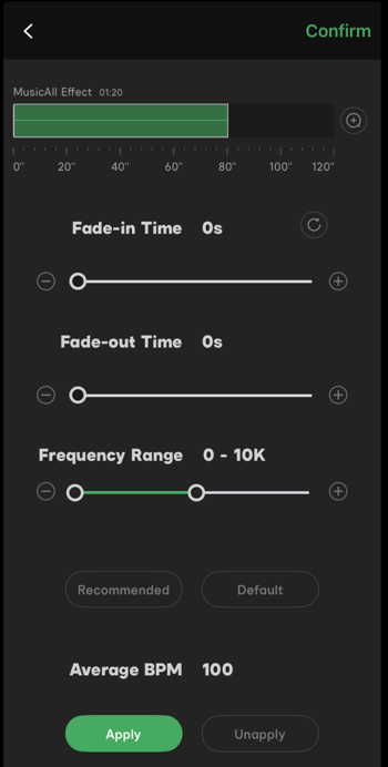
Figure 5.3.2.2 Audio Clip Information Page
5.3.2.3 Audio Clip Editing
- Tap the audio clip editing button
 to enter the audio clip editing page.
 - The buttons above the audio clip timeline are as follows: Timeline zoom in/out button , Rename button
 , Reset Timeline button
  and the Delete button
  .
. - The timeline zoom in/out button changes the timeline display units.
- The rename button can change and rename the current audio clips name in the pop-out window.
- The reset timeline button clears all of the clips on the timeline.
- The delete button deletes the selected audio clip.
- Move the left and right edges of the selection window to trim the audio clip in the audio editing window.
- On the audio clip editing page, users can adjust the lighting effect color mapping. For details, see the Lighting color mapping.
- On the audio clip editing page, users can adjust the lighting SAT, BPM and INT. For details see the SAT, BPM and INT.
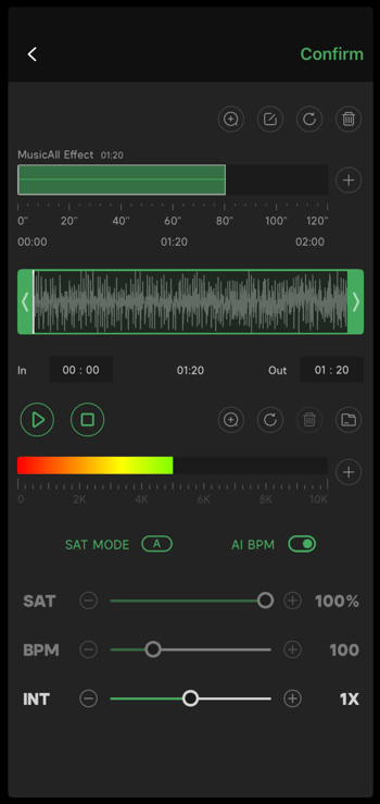
Figure 5.3.2.3 Audio Clip Editing Page
5.4 Color Mapping
- The app generates color mapping automatically, according to the audio hertz after importing the audio files.
- With color fixtures, users can choose HSI and CCT color mapping modes.
- With bi-color fixtures, users can only choose CCT color mapping mode.
- With daylight fixtures, the color will remain white and only the intensity will change.
5.4.1 Add Color Mapping
- Tap the Add Color Mapping button
 to enter the color mapping setting page.
 - Adjust the sliders to set the frequency range and assign the color or color range to the selected frequencies.
- Color mapping for different frequencies displays as color mapping clips in the color mapping window.
- If two color mapping settings cover the same sections, the latter one will overlay the previous one.
- Point: Effects will only change the intensity.
- Range: HSI/CCT will change along with the selected chase mode(sequential, reverse, alternating and random), within the selected range.
- On the color mapping setting page, users can save the color mapping to presets or apply the color mapping from presets.
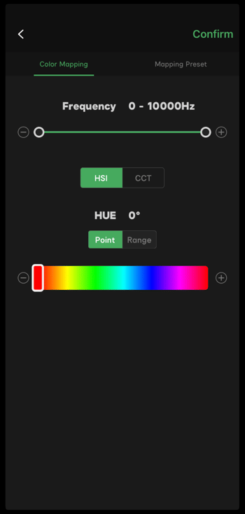
Figure 5.4.1 Color Mapping Window
5.4.2 Effect Control Buttons
- Tap the play button
 to start the effects playback, tap again to pause the effects playback. The pointer will stop at the current position.
 - Tap the stop button
 to stop the effects playback. The pointer will return to the beginning position.
 - Tap the cycle mode button
 to change the cycle mode.
 - In single-cycle mode, the cycle button displays as
 . The effects will stop and the pointer will return to the beginning after one play.
 - In repeat cycle mode, the cycle button displays as . The effects will automatically restart from the beginning after every play.
5.4.3 Color Mapping Manage Buttons
- The color mapping manage buttons are located above the color mapping window.
- Tap the zoom in/out button to change the display view of the color mapping window.
- Tap the reset button
 to clear all of the current color mapping data.
 - Select the clip in the color mapping window and tap the delete button
 to delete the selected clip.
 - Tap the color mapping save button
 to save the current color mapping.
 - When a saved mapping set is selected from Mapping Set, users can preview the mapping set at the top of the color mapping set interface.
- Users can add saved mapping sets to the album, rename or delete the saved mapping sets.
5.5 SAT, BPM and INT Adjustment
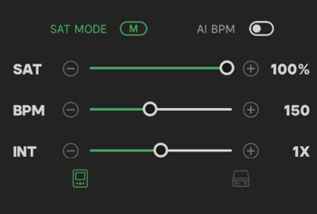
Figure 5.5 SAT, BPM and INT Adjustments
5.5.1 SAT
- Music FX has three saturation adjustment modes: Manual, Automatic and Random. Tap the
 button to select a modes.
 - In manual mode , users can adjust the saturation from 0-100% with the slider.
- In automatic mode
 , the App adjusts the saturation automatically.
 - In random mode
 , the saturation changes randomly within the selected range.
5.5.2 BPM
-
Music FX has two BPM modes: AI BPM or custom BPM.
-
In AI BPM mode
 , the App will match the BPM according to the audio clip;
 -
In custom BPM mode
 , users can adjust the BPM value from 30-3600 via the slider. When users use the plus/minus button to adjust the BPM value, the value increase/decrease as below:
| 30 | 60 | 72 | 75 | 80 | 90 | 100 | 112.5 | 120 | 144 | 150 | 180 | 200 | 225 |
|---|
| 240 | 300 | 360 | 400 | 450 | 600 | 720 | 900 | 1200 | 1800 | 3600 |
|---|
5.5.3 Intensity
- Users can adjust the fixtures' intensity from 0.1-10X via the slider or plus/minus buttons.
- When using the plus/minus buttons: If the intensity value is above 1X, then the intensity value will increase/decrease 1X. If the intensity value is below 1X, then the intensity value will increase/decrease 0.1X.
5.6 Store and Project
- User can rename, manage and delete saved effects in the store or project.
- The effects in store mode will save to the Store. Effects in project mode will save to Project.
- The effects data in Store mode and Project mode are not interchangeable.
- The cloud service does not support automatic cloud saving for Music FX effects.
- Effects data can only be saved locally.
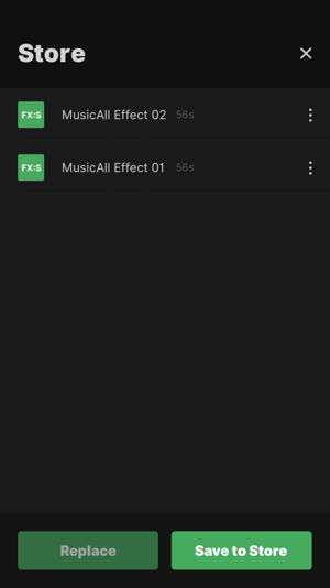 |
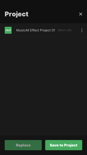 |
| Figure 5.6-1 Store | Figure 5.6-2 Project |