
1. Projects
Projects are the wireless network component of Sidus Link®. Users can control and manage fixtures after adding them to a Project.
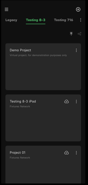 Figure 1 Projects List
1.1 Demo Project
Demo Project is a virtual Project for demonstrating Sidus Link® functions. With the Demo Project, users can simulate the actual workflow in Sidus Link®, even if users don't have lighting fixtures to connect and control.
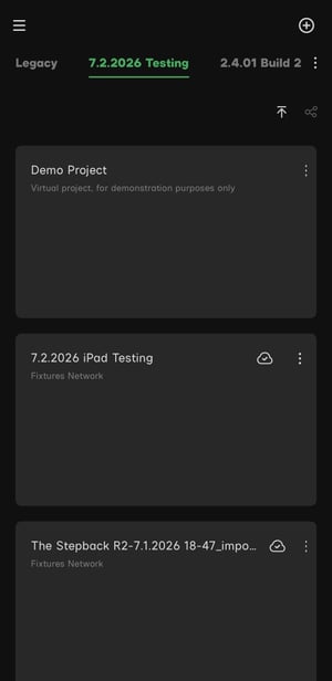 . Figure 1.1 Fixture list in the Demo Scene
Note:
- If users delete the Demo Project, please reinstall the App to recover.
- The Demo Project is a virtual project that is for demonstration purpose only. Users cannot connect actual fixtures in the Demo Scene.
- Please create a new project to connect lighting fixtures.
1.2 Project
Click the  button on the Project screen to create a new project. Tap the newly added Project to enter the fixture list. Users can then add fixtures to the project fixture list and control the fixtures.
1.3 Project Management
Users can rename, delete and share the project to a CC Group via the Project Management Menu.
Tap the menu button icon to open the Project Management Menu.
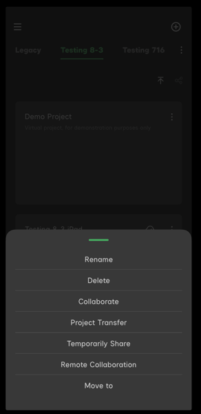
Figure 1.3 Project Management Menu.
1.3.1 Rename
Rename the the default Project title.
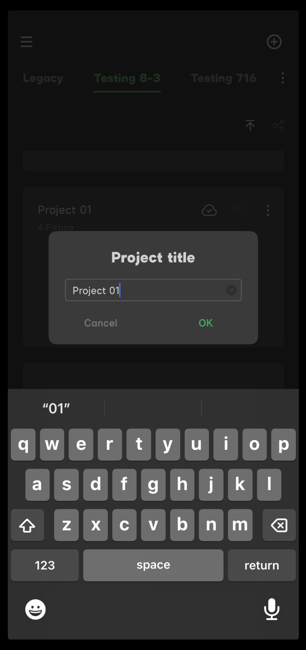
Figure 1.3.1 Rename the Project
1.3.2 Delete
Users can delete the Project in the Project Management Menu.
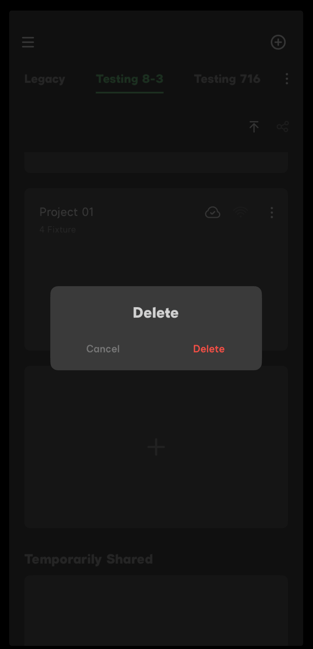
Figure 1.3.2 Delete the Project
Note:
The Project you deleted wouldn't be recover again.
1.4 Share the Project
Users can share the Project with team members via a CC Group.
All of the team members in the CC Group can view and control the shared Project.
- CC Group collaboration: Users won't able to share the Project until a CC Group is created. To create a CC Group, open the CC Group menu in the main menu.
- Members of CC Group need to click the refresh button icon at the bottom of the Project list to update the latest collaboration data.
- Temporary collaboration: Tap the code button icon to generate a four-digit code. Team members can tap the + button and enter the code to join the CC Group.
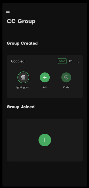
Figure 1.4 The shared Scene
Note:
- To use the CC Group collaboration function, please create a CC Group first.
- The collaboration code expires in 1 hour.
- The CC Group collaboration requires an internet connection for all members.
- When there is only one fixture in the project, users can still share the Project with team members, however, only one user can actually control the fixture at a time.
- Only the CC Group creator can manage the Project and add fixtures. Other team members can only control added fixtures.
- When the CC Group creator deletes fixtures in the shared Project, other team members will not able to control the deleted fixtures. To check the available fixtures, pull down on the fixture list to refresh.
- When the CC Group creator cancels the Project collaboration, the shared Project will be deleted when other members refresh the Project list. However, users need to delete the temporary collaborated Project manually.
2. Add Fixtures
Sidus Mesh® is a new decentralized wireless technology that allows the user to control the fixtures network without a router. With one smart device, users can control hundreds of lighting fixtures. Even if one of the fixtures has failed, users can still connect to the lighting fixture network stably.
Users need to add fixtures to the Project before using the lighting control system.
2.1 Prepare the Fixtures and the Smart Device
Reset the fixtures Sidus BT connection and turn on the smart device's Bluetooth before connecting fixtures to Sidus Link®.
If users are using an Android device, please turn on the GPS or location service.
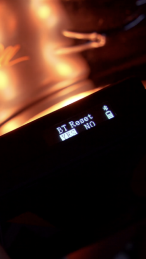 Figure 2.1 Reset the fixtures Bluetooth
Note:
- If the Android smart device doesn't have a GPS function, it will not be able to use the wireless lighting control functions.
- Please connect the fixtures via the Sidus Link® interface, not the fixtures system Bluetooth interface on the smart device.
2.2 Connect Fixtures
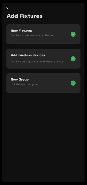
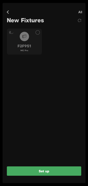
Enter the Add Fixtures interface by tapping the green "+" button in the fixture list interface to add new fixtures. The available fixtures will appear on the "New Fixtures" page.
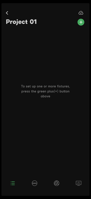 Fi
Fi
- Add new fixtures: Tap the Project card to enter the Project of your choice. Tap the
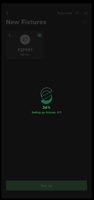
 at the top-right corner of the fixture list-enter the Add Fixtures page. Select the New Fixtures card, choose the fixture you'd like to add, then click "Set up" to add the fixture.
|
|
|
| Figure 2.2-1 Add New Fixtures | Figure 2.2-2 Select Fixtures | Figure 2.2-3 Waiting for Connection |
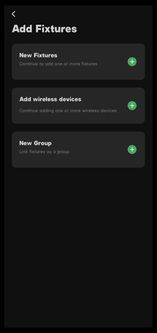
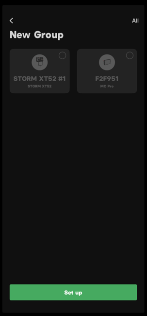
- Add new fixtures group: Tap the Project card to enter the Project of your choice. Tap the at the top-right corner of the fixture list-enter the Add Fixtures page. Select the New Group card, choose the fixtures you'd like to add, then click "Set up" to add the fixtures.
|
|
| Figure 2.2-4 Add New Fixtures | Figure 2.2-5 Add New Group |
2.3 Reconnect
Sidus Link® will notify you that the fixture is disconnected when there is an interruption. Tap "Reconnect" to re-establish the connection.
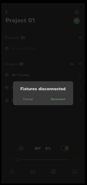
Figure 2.3 Fixture Reconnect
When re-openning a Project or switching between Projects, Sidus Link® App will reload the network and reconnect the fixtures.
Note:
- Online fixtures display with white letters and icons.
- Offline fixtures display with grey letters and icons.
- It takes time to reload and reconnect fixtures, please be patient.
- When reconnection fails, the fixture might be powered off or out of control range.
2.4 Fixture Locating
Users can use the fixture locating button to locate a fixture.
Tap the fixture locating button  , the fixture or a group of fixtures will flash.
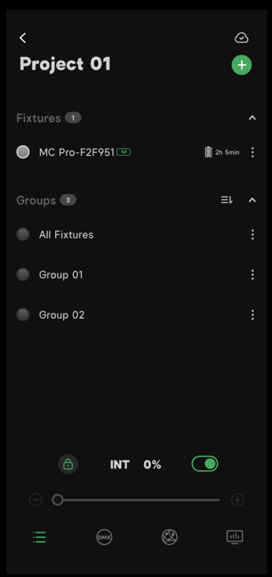
Fixture 2.4 Fixture Locating Button
2.5 Fixture Management
Users can manage lighting fixtures in the fixture list.
- Power Management
- Users can check the power source and battery life in the fixtures list.
- There are two types of power sources: Battery and AC power.
- With battery
 : The fixture is powered by batteries. The battery status and estimated battery life are displayed after the fixture's name.
 - AC power
 : The fixture is powered by an AC adapter.
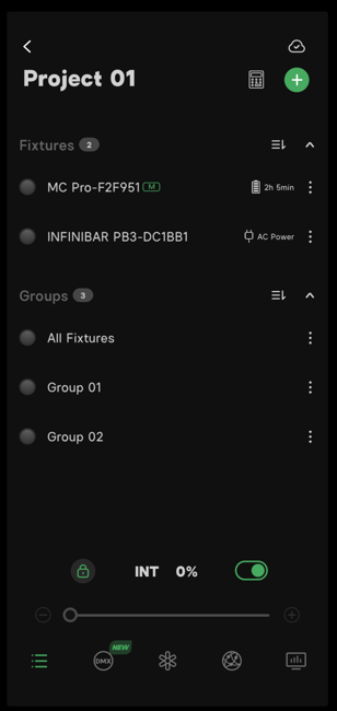
Figure 2.5-1 Power Source
- Fixture Management
- Tap the menu button icon after the fixture's name to open the fixture's management menu.
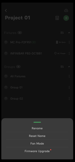
- Menu of the master node fixture: Rename, Reset Name, Fan Mode and Firmware Upgrade.
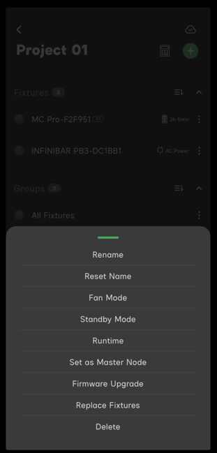
- Menu of other fixtures: Rename, Reset Name, Fan Mode, Standby Mode, Runtime, Set as Master Node, Firmware Upgrade, Replace Fixtures and Delete.
|
|
| Figure 2.5-2 Menu of the Master Node Fixture | Figure 2.5-3 Menu of Other Fixtures |
Note:
- The fixture will reset Sidus BT automatically after being deleted from the Project.
- The fixture with a green "M" is the master node fixture. The master node fixture cannot be deleted.
- Fan mode management is available for fixtures with a fan.
- When there is a red dot on "Firmware Upgrade", please update the firmware.
2.6 Fixtures Group
Sidus Link® generates a default "All Fixtures" group when users create a new Project.
Users can select multiple fixtures and group them as a new Fixture Group.
- All fixtures management: Console. Details see 4. Console and preset;
- Group management menu: Console, Rename, Edit, White Light Standard, Delete and choose an identifying color tag.
- Edit a created group: Users can edit the created group. For example, you can add or delete fixtures.
- Fixtures group color tag function: Users can add a color tag to the fixtures group.
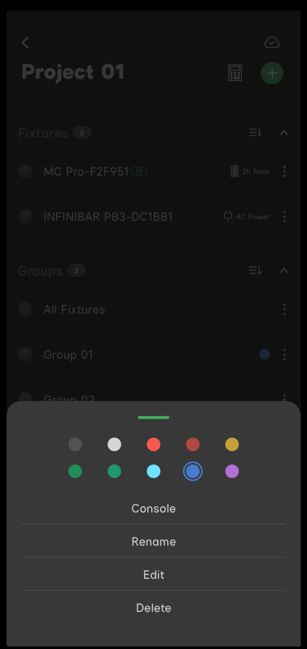
Figure 2.6 Fixture Group Management Menu
Note:
- If there are different types of fixtures in one fixtures group, the available features are dependent on the fixture with fewer functions. For example: If a daylight fixture is grouped with bi-color and color-pro fixtures, only the daylight features will be available for the fixtures group.
- Make sure all the fixtures are online before creating a fixtures group.
3. Presets
Users can save their favorite parameters and settings for fixtures as Presets. It allows users to adjust active lighting parameters quickly. With an internet connection, all presets can be synchronized to the Sidus Link® Cloud Service.
Tap the Presets cube at the top-right corner to enter the presets interface and save the current lighting parameters.
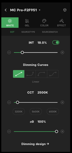
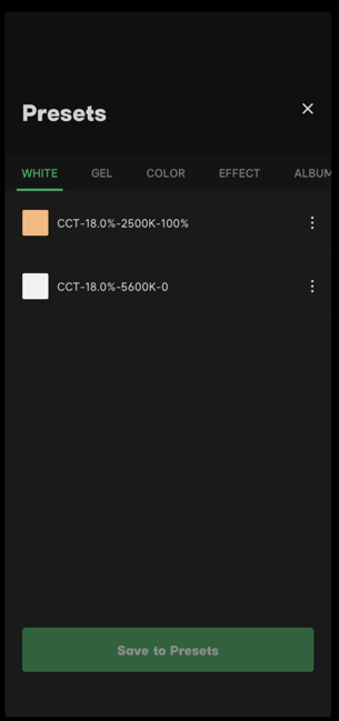
Figure 3.1 Presets Cube Figure 3.2 Presets Menu
3.1 Presets Management
Presets are sorted by the lighting control modes. Tap the presets management menu  to manage it.
The Management Menu for Presets includes these options: Rename, Add to Album & Delete.
Users can preview the Preset details via the Preset Management Menu.
Note:
- Tap "Save to Presets" to save a Preset.
- After selecting a Preset, tap "OK" to apply the Preset.
- Presets for SidusPro® FX request start the saved effect when "Ok" is tapped.
- There are color swatches beside the saved presets for quick identification.
- Presets can only run on the same type of fixtures. For example, the Presets from daylight fixtures are only available for daylight fixtures.
3.2 Album for Presets
Users can save Presets to an Album for quick use.
- Tap "Add to Album" in the Preset menu to save the selected Preset to an Album.
- Album Management Menu options: Rename and Remove from Album.
- The Preset in an Album will be deleted when the user deletes the original Preset. However the original Preset won't be deleted when users remove the Preset from the Album.
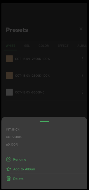
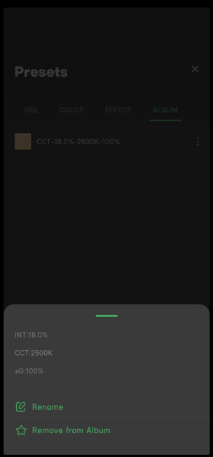
Figure 3.2.1 Add to Album Figure 3.2.2 Album Options
4. Console and Quickshots
To enter the Console interface, tap the "computer monitor" Console icon in the bottom-right corner of the Fixtures menu.
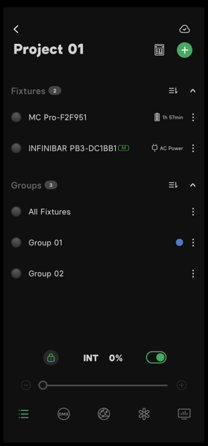
Figure 4.1 Console Icon
4.1 Console
The Console interface is a convenient lighting control interface that allows users to control fixtures.
Sidus Link® provides three control modes in Console: Console, PALETTE and Quickshots.
- In Console Mode, slide the fixture slider to adjust the intensity of a fixture.
- Tap and hold a slider, then slide it up or down to adjust the fixture order.
- Tap the control icon on the left side of the fixture slider to enter the lighting control system for that fixture.
- Users can save the parameter levels set with Console, to Presets.
- Tap the lock mode icon
 to enter the console lock mode. Tap the lock all button
  , to lock the "All Fixtures" slider at the bottom of the console interface.
 - The locked fixtures will remain in the same setting and users won't able to slide to change the brightness of the All Fixtures Slider. User can still change the levels of individual fixture sliders while locked.
- Tap the lock all button to unlock all the fixtures, which restores the users ability to use the All Fixtures slider to change the brightness of all fixtures.
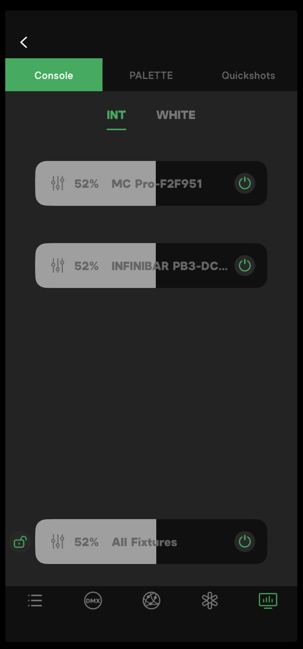
Figure 4.1-1 The Console Interface
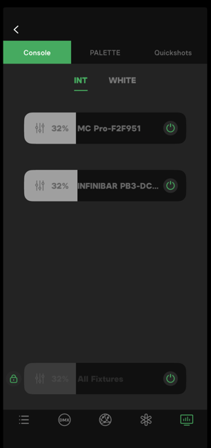
Figure 4.1-2 Console Lock Mode
4.2 INT Mode
In INT mode, users can only modify the intensity; the CCT and color will remain the same.
4.3 White Mode
When using White mode, the CCT of all fixtures will change to 5600K.
4.4 PALETTE
The Palette interface offers several color control styles: HSI, CCT and Multi modes.
4.4.1 Add Palette fixtures
Enter the PALETTE interface via the console page and Add Palette Fixtures to get started.
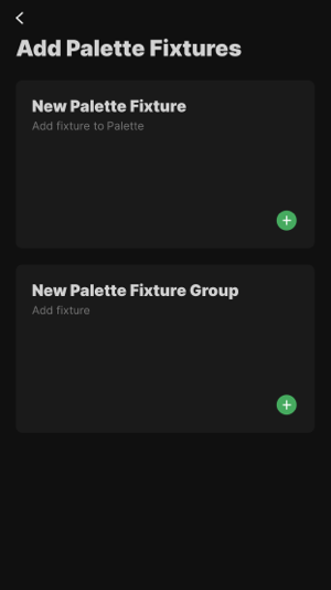 |
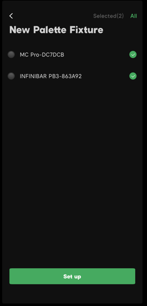
|
| Figure 4.4.1-1 Add New Palette Fixture or New Palette Fixture Group | Figure 4.4.1-2 Select New Palette Fixture |
4.4.1.1 Add New Palette Fixtures
- Tap the plus mark at the bottom of the Palette interface to add New Palette fixtures.
- The newly added fixtures display at the bottom of the Palette interface.
Note:
Users need to add fixtures to the Project fixture list first, then the fixture will be available for the Palette interface.
4.4.1.2 Add New Palette Fixture Group
- Tap the plus mark at the bottom of the Palette interface to add a new Palette fixture group.
- The newly added fixture group is displayed at the bottom of the Palette interface.
4.4.2 Palette Style
Users can adjust color source type, color scheme style and set the number of color dots in the Palette style interface.
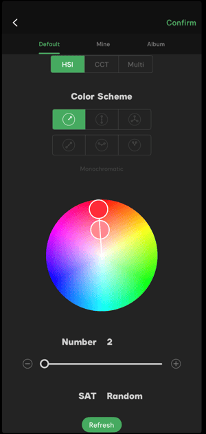
Figure 4.2.2-1 Palette Style
4.4.2.1 HSI
The color scheme styles in the HSI mode are Monochromatic, Complementary, Triad, Split Complementary, Contrast Color and Analogous.
Monochromatic:
- In Monochromatic mode, Palette generates color dots with the same hue but different saturation values.
- The generated color dots have random saturation values, and users won't able to adjust the saturation values manually.
- In Monochromatic mode, the minimum amount of color dots is 2 and the maximum amount of color dots amount is 12.
Complementary:
- In Complementary mode, Palette will generate two hues with color values 180° opposite of each other on the color wheel and with different saturation values.
- The generated color dots have random saturation values and users won't able to adjust the saturation values manually.
- In Complementary mode, the minimum amount of color dots is 2 and the maximum amount of color dots is 12.
Triad:
- In Triad mode, Palette will generate two hues with color values 120° offset from each other on the color wheel and with different saturation values.
- The generated color dots have random saturation values and users won't able to adjust the saturation values manually.
- In Triad mode, the minimum amount of color dots amount is 3 and the maximum amount of color dots is 12.
Split Complementary:
- In Split Complementary mode, Palette will generate two hues with color values 180° offset on the color wheel and with different saturation values.
- Users can adjust the saturation values manually or choose random mode.
- In Split Complementary mode, the minimum amount of color dots is 2 and the maximum amount of color dots is 12.
Contrast Color:
- In Contrast Color mode, Palette will generate two hues with color values 120° offset on the color wheel and with different saturation values.
- Users can adjust the saturation values manually or choose random mode.
- In Contrast Color mode, the minimum amount of color dots is 2 and the maximum amount of color dots is 12.
- In Analogous mode, Palette will generate two hues with color values 60° offset on the color wheel and with different saturation values.
- Users can adjust the saturation values manually or choose random mode.
- In Analogous mode, the minimum amount of color dots is 3 and the maximum amount of color dots is 12.
4.4.2.2 CCT
The Color Scheme styles in CCT mode are Split Complementary, Contrast Color and Analogous.
Split Complementary:
- Users can adjust the green/magenta values of the generated color dots manually or choose random mode.
- In Split Complementary mode, the minimum amount of color dots is 2 and the maximum amount of color dots is 12.
Contrast Color:
- Users can adjust the green/magenta values of the generated color dots manually or choose random mode.
- In Contrast Color mode, the minimum amount of color dots is 2 and the maximum amount of color dots is 12.
Analogous:
- Users can adjust the green/magenta values of the generated color dots manually or choose random mode.
- In Analogous mode, the minimum amount of color dots is 2 and the maximum amount of color dots is 12.
Note:
If the lighting fixtures do not support the selected color temperature value, the App will adjust to the available color temperature value for the fixture.
4.4.2.3 Multi
In Multi mode, users can choose color dots from both HSI and CCT parameters.
- In HUE-CCT/CCT-HUE mode, Multi will assign colors in the order of HUE in the front and CCT in the back / CCT in the front and HUE in the back.
- Adjust the slider to choose the amount of color dots for HUE and CCT.
- The color scheme modes for Multi mode are Split Complementary, Contrast Color and Analogous. For HUE mode color scheme, please refer to 4.4.2.1 HSI. and for CCT mode color scheme, please refer to 4.4.2.2 CCT.
- Users can set the HUE value manually or choose random HUE value mode.
- Users can adjust the CCT value manually or choose random CCT value mode.
4.4.2.4 Mine and Album
Users can save the set color scheme style to "Mine" and they can also save the color scheme style to "Album" for quick selection.
4.4.3 Color Scheme Link Setting
- Color Scheme Link Setting is enabled: As users adjust a single color dot, the relevant color dots will change together.
- Color Scheme Link Setting is disabled: As users adjust a single color dot, only the parameter of that color dot will change.
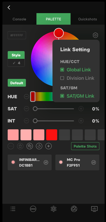
Figure 4.4.3-1 Link Setting
4.4.3.1 HUE/CCT
- Global Link Enabled: When users adjust the HUE/CCT for a single color dot, all other color dots will change accordingly.
- Division Link Enabled: When users adjust the HUE/CCT for a single color dot, only the relevant color dots will change.
Note:
Global Link and the Division Link are mutually exclusive; users can only choose one type of link mode.
4.4.3.2 SAT/GM Link
- SAT/GM Link can only be enabled after HUE/CCT Link is enabled.
- When users adjust the parameters for a single color dot, all other color dots will change accordingly.
4.4.4 Color Assign Mode
- The generated color dots will assign to the color allocation area by the default order and automatically assign to the fixtures along with the selected assign mode.
- Tap the Color Assign Mode button
 to choose Default, Custom or Random mode from the drop menu.
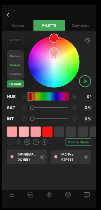
Figure 4.4.4-1 Color Assign Mode
4.4.4.1 Default Mode
-
In Default Mode, Palette will assign colors to the fixture from the left side to the right side in the displayed order.
-
The colors will be displayed on the fixture cards. If the number of colors on the color cubes cannot match the number of the fixtures, then the exact match of either party shall prevail.
4.4.4.2 Custom Mode
- In Custom Mode, Palette will not assign colors to the fixture, users need to select and assign the color cubes manually. The colors will be displayed on the fixture cards.
- When users assign the color cubes manually. The color assign mode will change to Custom Mode automatically.
4.4.4.3 Random Mode
- In Random Mode, Palette will assign colors to the fixture in random order. The color will be displayed on the fixture cards.
- The color wheel will be refreshed every time users tap the random mode.
4.4.5 Color Wheel and Adjustment
4.4.5.1 Color Wheel
- The Color Wheel will display the designated amount of the color dots based on the selected mode. Drag one of the color dots and the other color dots will change according to the selected link mode.
- The HUE and SAT value will change along with the color dots on the color wheel.
- The color cubes below the color wheel will change simultaneously with the color dots on the color wheel.
4.4.5.2 Play Button
- The generated color cubes will pre-load to the fixture and display on the fixture cards as color dots. The exact lighting color won't synchronize with the pre-loaded color.
- Tap the Play button
 beside the color wheel and the fixture will display the chosen color.
 - When the fixture does not support the assigned color, the App will auto modify the color.
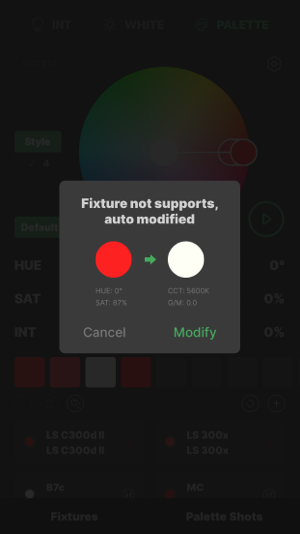 Figure 4.4.5.2 Color Auto-Modification
4.4.5.3 HUE, SAT, and INT Adjustment
- The HUE, SAT and INT adjustment sliders are located below the color wheel.
- Select the color dot on the color wheel to adjust the HUE, SAT and INT.
- If Link Mode is on, the relevant color dots will change accordingly. Details see 4.4.3 Color Scheme Link Setting.
4.4.6.1 Fixture Card Management
Select the fixture card, tap the menu button  to rename, reset the name or delete the fixture card.
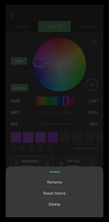 Figure 4.4.6.1 Fixture management menu
4.4.6.2 Remove the Current Color Scheme
- Remove color scheme from a single fixture: Select the fixture card, tap the remove button
 to remove the current color and reset the light to white.
 - Remove color scheme for all fixtures: Tap the remove all button
 to remove the current color scheme and reset all the lights to white.
4.4.6.3 Reset and Add Palette Fixtures
- Tap the reset button
 to clear all the added fixtures and groups.
 - Tap the add button
 to add fixtures or fixture groups to the Palette.
 - Hold and drag the fixture card to re-arrange the fixture order.
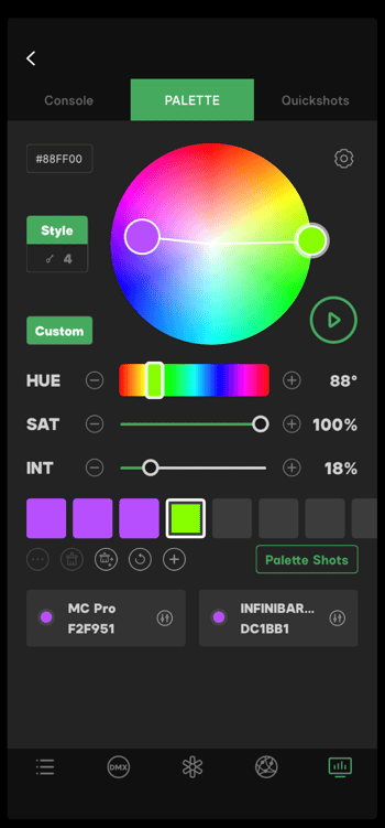 Figure 4.4.6.3 Fixtures Management
4.4.6.4 Manually Assign a Color
- Select the color cube and tap the fixture card or hold and move the color cube then release it on the fixture card. The fixtures will display the color immediately.
- When choosing a color on the color cube, the corresponding color dot on the color wheel will be selected as well.
- Tap to select the color cube, tap again to cancel the selection.
- Select the fixture card and tap the parameter management button
 to enter the parameter adjustment interface, users can adjust the HUE, SAT, and INT.
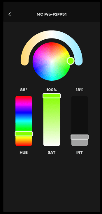
Figure 4.4.4.6-1 Fixture Management
4.4.7 Palette Shots
- After finishing the lighting color scheme, users can save the color style to Palette Shots.
- Tap the color scheme preset management button
 to rename, manage or delete the Palette shot.
 - Tap the Palette shot to preview its details on the top of the Palette Shots page.
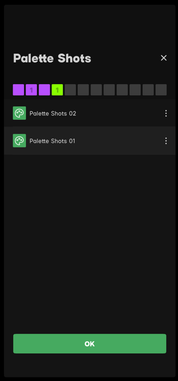 Figure 4.4.7 Palette Shots
4.5 Quickshots
- There can be multiple lighting looks for one set. Quickshots are created to enable quick lighting look implementation.
- Users can save multiple lighting looks in one Project, save the plans to Quickshots, then tap the quick shots to switch the lighting looks with one click.
- Users can rename or delete the Quickshots in the Quickshots management menu.
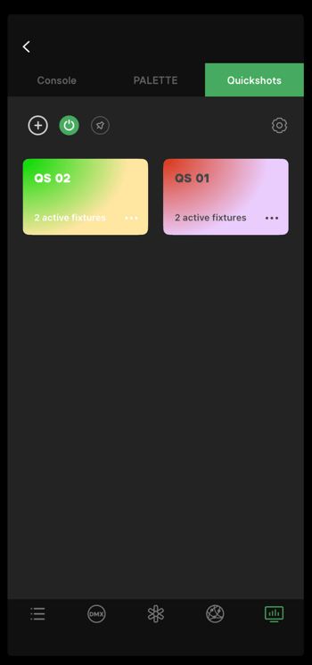 Figure 4.5 Quickshots
Note:
- Quickshots cannot be applied to another Project.
- When a Project is deleted, the Quickshots in the project will be deleted.
5. Types of Fixtures Sidus Link® Supports
Sidus Link® is compatible with all Sidus Mesh® enabled fixtures:
Daylight, Bi-Color, X, Full-Color fixtures and Sidus Bridge™.
5.1 Daylight Fixtures
There are two modes for Daylight fixtures: White and Effect:
- White Mode: Daylight only light output
- Effects Mode: 24 built-in system effects
5.2 Bi-Color Fixtures
There are three modes for Bi-Color fixtures: White, Gel and Effect:
- White Mode: CCT and Source Type
- Gel Mode: CTO/CTB options
- Effects Mode: 24 built-in system effects
5.3 X Fixtures
There are four modes for X fixtures: White, Gel, Color and Effect.
- White Mode: CCT and Source Type
- Gel Mode: CTO/CTB options
- Color Mode: HSI and Color Picker
- Effects Mode: 24 system built-in effects
5.4 Full-Color Fixtures
There are four modes for Full-Color fixtures: White, Gel, Color and Effect:
- White Mode: CCT and Source Type
- Gel Mode: CTO/CTB, and Gel options
- Color Mode: HSI, RGB, xy and Color Picker functions
- Effects Mode: 24 system built-in effects
5.5 Sidus Bridge™
Sidus Bridge™ is designed for legacy Aputure® fixtures. With a Sidus Bridge™, users can connect and control legacy Aputure® 2.4G fixtures through Sidus Link®.
- White Mode: CCT
- Console Mode
- Effects Mode: 24 built-in system effects and Picker FX®
- Settings: Set the channel and group that are controlled by Sidus Bridge™.
6. Firmware Update via OTA
Sidus Link® is compatible with all new Aputure fixtures and other Partner Brand Fixtures, including LS 600d Pro, LS 300d II, B7c and MC etc. Firmware updates via the Sidus Link® OTA service are available.
OTA firmware updates are also available for Sidus Bridge™ and legacy fixtures that can connect to Sidus Link® via Sidus Bridge™.
- Select "Firmware Update" in the fixture management menu. Sidus Link® will check for available updates. Tap the "Update Now" button to update the firmware.
- Keep the smart device close to the fixture during the firmware update process.
- If updating fails, check the internet and Bluetooth connection status and try again.
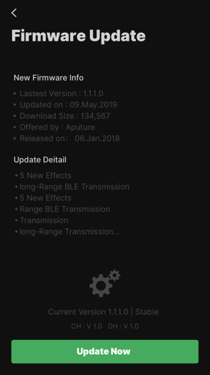 Figure 6 Firmware update
Note:
Make sure that the smart device and the fixture have sufficient battery power or are connected to AC power during the firmware update process.
7. Compatible with Prolycht
Sidus Link® is compatible with Prolycht. When adding Prolycht devices in the scene, the Prolycht device list will be displayed. If there are both Aputure/amaran and Prolycht devices present, they will be shown in two separate columns.
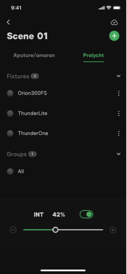 Figure 7 Prolycht
7.1 Add Device
Enter the scene, click the '+' in the upper right corner, select 'New Fixtures,' choose the device you want to add, and complete the addition. (A scene can only have a maximum of 7 Prolycht devices).
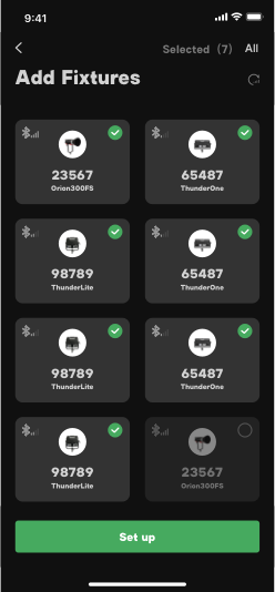 Figure 7.1 Add Device
7.2 Add Group
Enter the scene with Prolycht devices, click the '+' in the upper right corner, select 'New Group,' choose the lights for a custom combination. (Prolycht devices can be grouped with other Prolycht devices but cannot be grouped with Sidus Link devices).
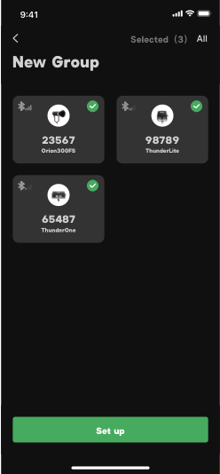 Figure 7.2 Add Group
7.3 White Mode
7.3.1 CCT
Users could change the intensity, color temperature and G/M parameters in the sliders interface.
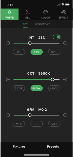 Figure 7.3.1 CCT
7.3.2 Source type
In the Source type mode, we provide you with 46 common light source types for you to choose from.
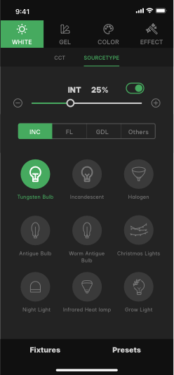 Figure 7.3.2 Source type
7.4 Gel Mode
7.4.1 Gel
Sidus Link® provides more than 300 types of LEE® and ROSCO® gels* for users to create professionally. (Users could search a gel with name and numbers or filter the gels by series, number, name and color.)
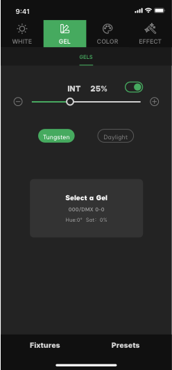 Figure 7.4.1 Gel
7.5 Color Mode
7.5.1 HSI
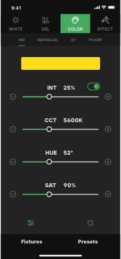
There are two types of interface in the HSI function: Slider and Color Wheel.
Slider interface:
- INT: from 0% to 100%
- CCT: Different devices may have different adjustable ranges
- HUE: from 0°(Red) to 359.9°
- SAT: from 0% to 100%
 |
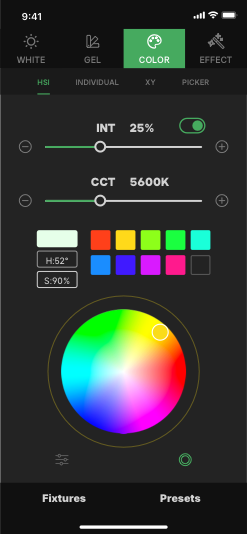 |
| Figure 7.5.1.1 HSI-Slider | Figure 7.5.1.2 HSI-Color wheel |
Color wheel interface:
- INT: from 0% to 100%
- CCT: Adjust Color Temperature
- Color Wheel: Users can adjust the hue by choosing different positions on the wheel. Users can adjust the color saturation by moving closer to or further away from the center of the color wheel.
7.5.2 xy
- In xy mode, there are three choices: Full gamut, Rec.2020 and Rec.709
- Gamut switch: Full gamut, Rec.2020 and Rec.709
- Coordinates: The xy value matches the exact color in the CIE1931 color system. Change the value of xy to produce a new color. Users can tap choose a color on the xy graphical interface.
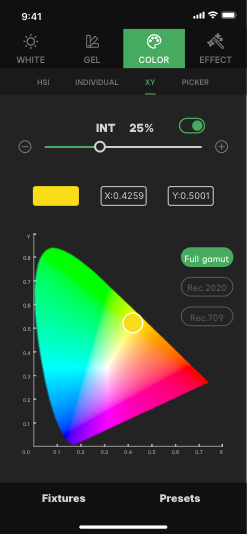 Figure 7.5.2 xy
7.5.3 Individual
Manually adjust the values of R, G, B, W and A, to obtain the desired color combination.
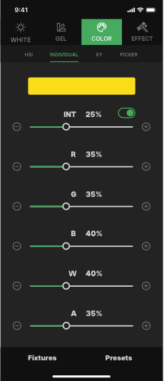 Figure 7.5.3 Individual
7.5.4 Calibrated
Manually adjust the values of R, G, B, W, CCT, and G/M to create the desired color combination.
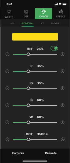 Figure 7.5.4 Calibrated
7.5.5 Picker
With the Color Picker function, users can point the camera to a color and then click the "Pick up" to pick the color. The picked color will apply to the fixture automatically.
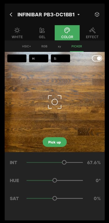 Figure 7.5.5 Color Picker
7.6 Effect Mode
7.6.1 System
The built-in system effects include 24 preset lighting effects. Each effect allows adjustment of relevant parameters independently.
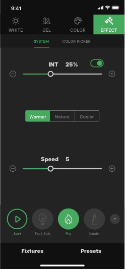 Figure 7.6.1 System Effects
7.6.2 Picker FX
By using the camera of a smart device to capture a color-changing action of a target, you can apply it to the fixture and execute that lighting effect.
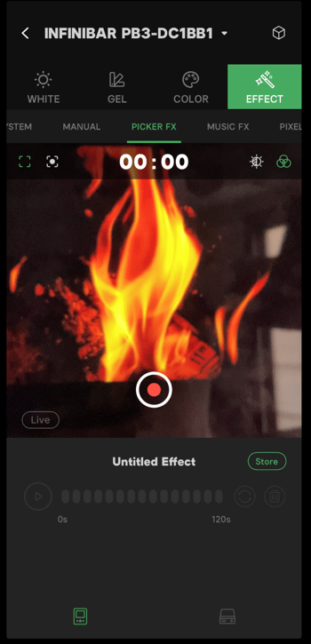 Figure 7.6.2 Picker FX
7.7 Preset
Users can save their favorite parameters and settings of the fixture as Presets. It allows users to adjust lighting parameters quickly. Prolycht presets are saved locally and do not transfer with the account.
Tap Presets at the top-right corner to enter the presets interface and save the current lighting parameters to a preset.
The lighting presets for Prolycht products are independent of those of Aputure/amaran products and do not affect each other.
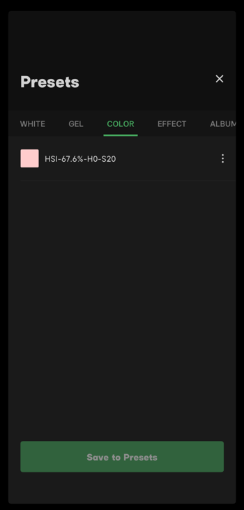 Figure 7.7 Presets
7.8 Note
Prolycht products do not support Magic Program Pro/Go, Magic Infinibar FX, Console, Palette or Quickshots.